Wiring
‑131‑
3.9.3 Wiring of RS232 Communication with PC
You can connect the servo drive and the PC using the PC communication cable during
RS232 communication. It is recommended to use RS232 communication interface.
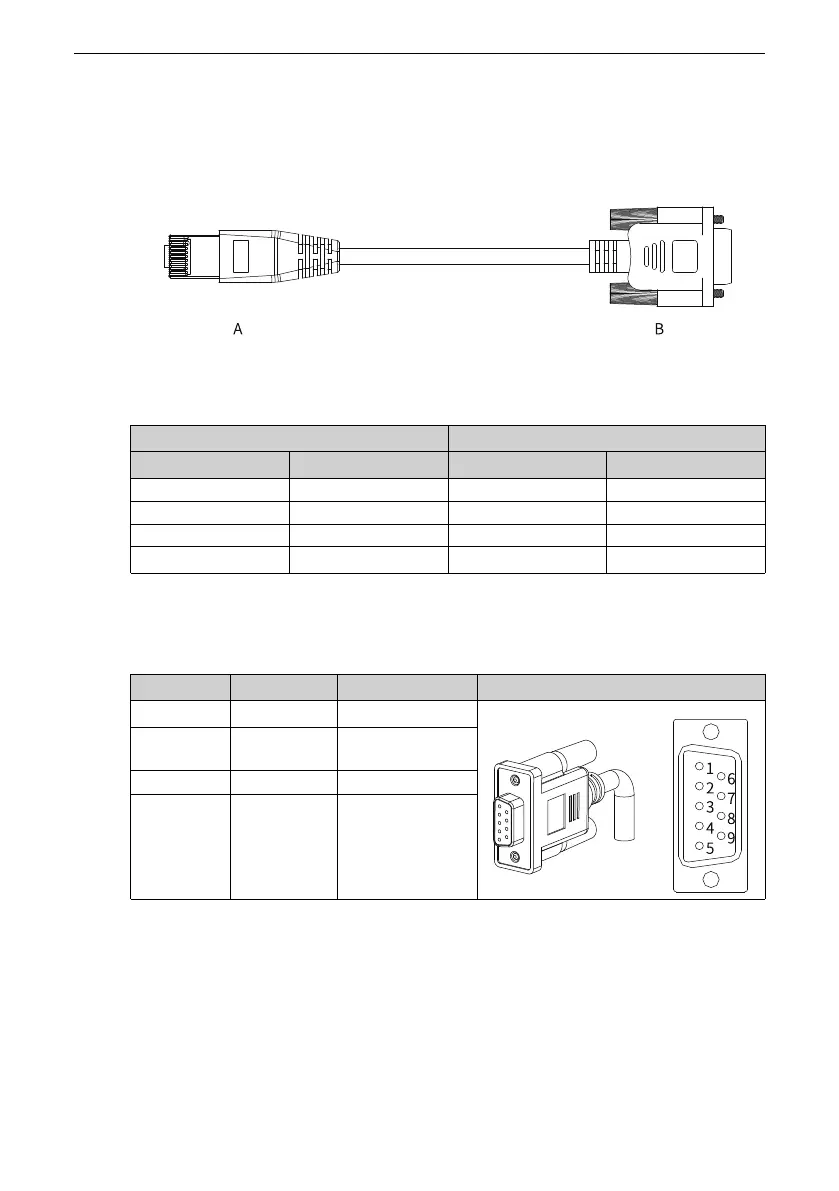
The outline drawing of the PC communication cable is shown in the following figure.
Figure 3‑45 Outline drawing of the PC communication cable
Table 3–38 Pin connection relation between the servo drive and PC communication cable
RJ45 on the Servo Drive Side (A) DB9 on the PC Side (B)
Signal Name
Pin No.
Signal Name
Pin No.
RS232‑TXD 6 PC‑RXD 2
RS232‑RXD 7 PC‑TXD 3
GND 8 GND 5
PE (shield)
Enclosure
PE (shield)
Enclosure
Pin assignment of DB9 terminal on the PC side is shown in the following table.
Table 3–39 Pin assignment of DB9 terminal on the PC side ("B" in the preceding figure)
Pin No.
Assignment Description Terminal Pin Layout
2 PC‑RXD
PC receiving end
3 PC‑TXD
PC transmitting
end
5 GND
Ground
Enclosure
PE
Shield
If the host controller supports USB interface only, use the serial‑to‑USB cable.

 Loading...


