Product Information
‑23‑
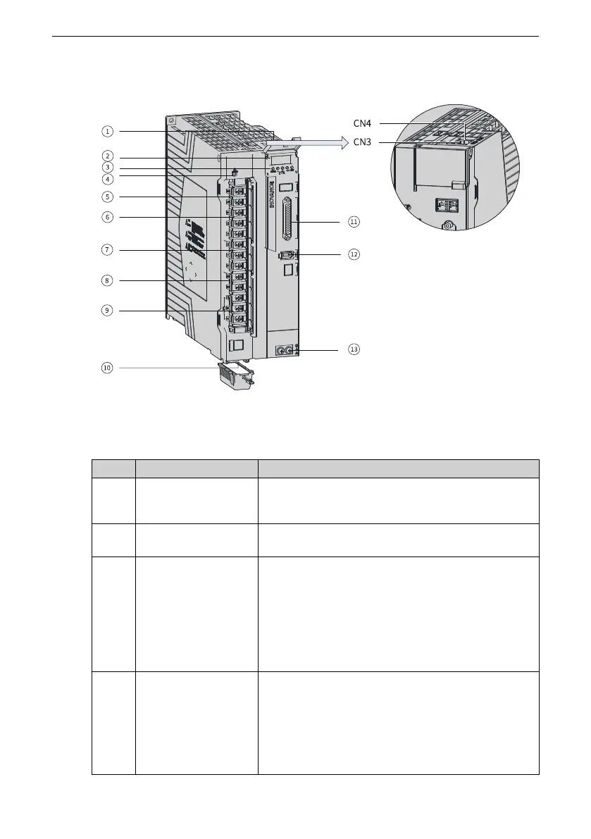
1.4.4 Servo Drives in Size E (Rated Power: 5.0 kW to 7.5 kW)
Figure 1‑11 Components of servo drives in size E (SV660PT017I, SV660PT021I, SV660PT026I)
Table 1–5 Description of components (SV660PT017I, SV660PT021I, SV660PT026I)
No. Name
Description
1
CN3, CN4
(communication
terminals)
Connected to RS232 and RS485 host controllers in
parallel.
2
5‑digit LED display
Used to display the servo drive operating status and set
parameters.
3
Keys
MODE: Used to switch parameters in sequence.
△: Used to increase the value of the blinking bit.
▽: Used to decrease the value of the blinking bit.
◁: Used to shift the blinking bit leftwards.
(Hold down: Turning to the next page when the
displayed number exceeds five digits)
SET: Used to save modifications and enter the next
menu.
4
CHARGE (bus voltage
indicator)
Used to indicate the electric charge is present in the
bus capacitor. When this indicator lights up, it indicates
the electric charge may be still present in the internal
capacitor of the servo drive even though the main
circuit power supply is switched off.
To prevent electric shock, do not touch the power
supply terminals when this indicator lights up.

 Loading...


