Appendix 2 Common EMC Problems and Solutions
‑153‑
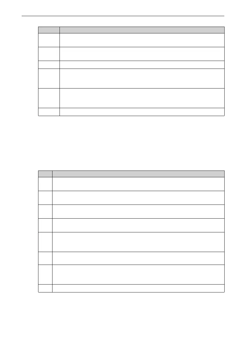
No. Measure
3
Connect the PE terminal of the drive to the PE terminal of the mains power
supply.
4
Add an equipotential bonding grounding cable between the host controller and
drive (see “
Figure 3–26
”
on page 96
).
5
Separate signal cables from power cables with a distance of at least 30 cm.
6
Install the ferrite clamp or wind the magnetic ring on the signal cable by one or
two turns. (see “
2.3.4 Instructions for Installing Magnetic Ring and Ferrite
Clamp
”
on page 53
).
7
Install the magnetic ring on the output side (UVW) of the drive by two to four
turns (see “
2.3.4 Instructions for Installing Magnetic Ring and Ferrite Clamp
”
on
page 53
).
8
Use shielded power cables and ground the shield properly.
6.3.2 I/O Signal Interference
The drive generates strong interference during operation. Although EMC measures are
taken, interference may still exist due to improper wiring or grounding during use.
When the drive disturbs or is disturbed by other devices, adopt the following
measures.
No. Measure
1
Use shielded I/O signal cables with the shield connected to the PE terminal. For
details, see “
3.8.1 Wiring of I/O Signal Cables
”
on page 108
.
2
Connect the PE terminal of the motor to the PE terminal of the drive, and connect
the PE terminal of the drive to the PE terminal of the mains power supply.
3
Add an equipotential bonding grounding cable between the host controller and
drive (see “
Cabinet system grounding
”
on page 95
).
4
Install the magnetic ring on the output side (UVW) of the drive by two to four turns
(see “
2.3.4 Instructions for Installing Magnetic Ring and Ferrite Clamp
”
on page 53
).
5
Increase the capacitance of the capacitor for low‑speed DIs. A capacitance up to
0.1 uF is recommended, as shown in “
Figure 6–2 I/O signal cables with capacitance
increased
”
on page 154
.
6
Increase the capacitance of the capacitor between AI and GND. A capacitance up to
0.22 uF is recommended.
7
Install a ferrite clamp or wind a magnetic ring on the signal cable by one or two
turns. (see “
2.3.4 Instructions for Installing Magnetic Ring and Ferrite Clamp
”
on
page 53
).
8
Use shielded power cables and ground the shield properly.

 Loading...


