Wiring
‑96‑
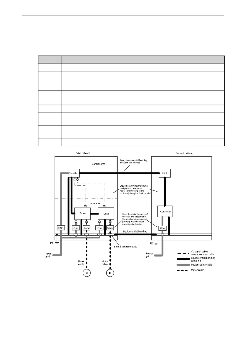
the disturbance source, and install devices into corresponding areas based on the
requirements listed in the following table.
Table 3–18 Wiring requirements
No.
Wiring requirements
1
Install the control devices and drive devices into two separate cabinets.
2
For installation involving multiple cabinets, use the grounding cable with a
cross‑sectional area of at least 16 mm
2
to connect the cabinets. This is to
ensure equipotentiality between the cabinets.
3
For installation involving only one cabinet, install different devices into
different areas inside the cabinet according to the signal intensity.
4
Apply equipotential bonding to devices in different areas inside the cabinet.
5
Shield all the communication (such as RS485) cables and signal cables routed
out from the control cabinet.
6
Install the power input filter inside the cabinet to a place near the input
interface of the cabinet.
7
Apply spray coating to all the grounding points in the cabinet.
Figure 3‑26 Recommended wiring of the cabinet system

 Loading...


