This document contains proprietary and confidential information of Integra LifeSciences Corporation. Integra’s confidential information may not be used, disclosed or reproduced without the prior wrien consent of Integra LifeSciences Corporation.
CUSA® Clarity System Service and Maintenance Manual Page 57 of 117 0645403-2-EN
WARNING
When measuring equipment leakage current of Class I ME equipment, an interruption of the grounding connection endangers system technicians and
bystanders.
NOTE
The Direct Method delivers erroneous values when supplied by an IT power system.
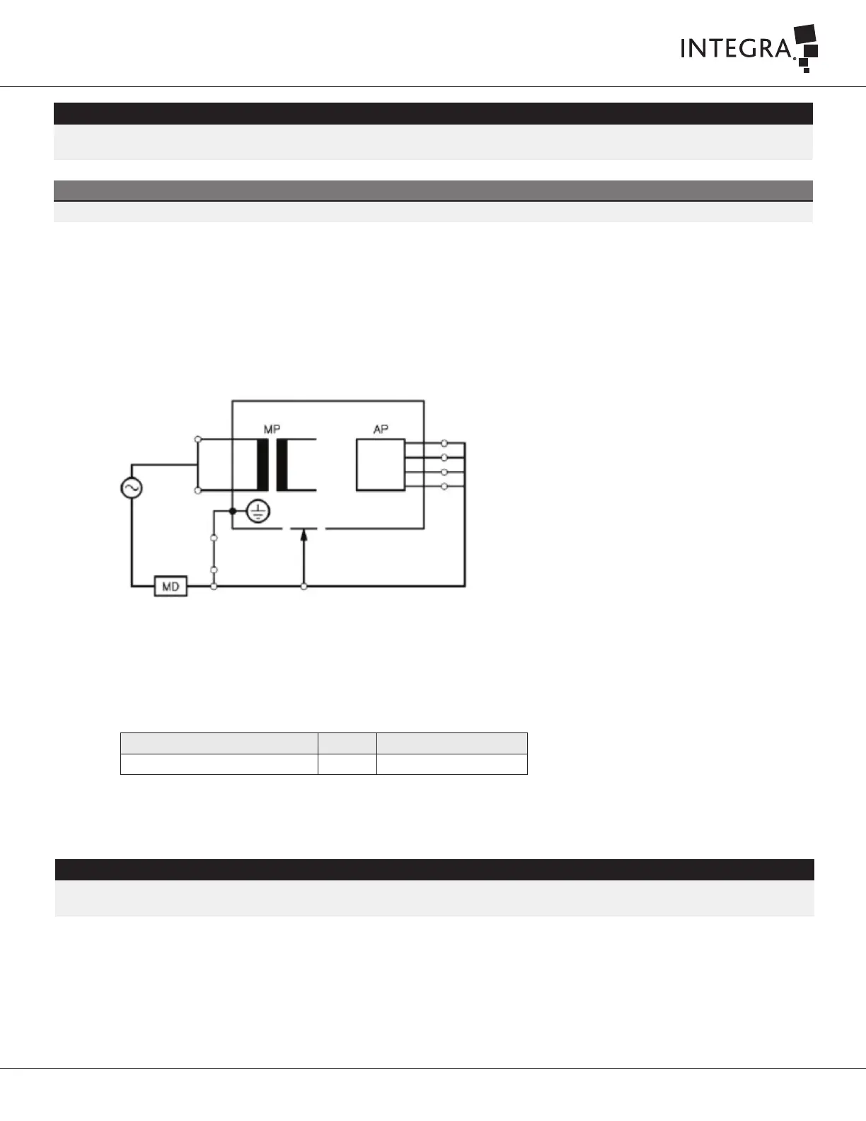
(b) IT-System (Alternative Method)
1. Connect the Safety Analyzer to the power source for an IT-System.
2. Connect the console to the main power socket of the Safety Analyzer.
3. Aached the crocodile clip from the Safety Analyzer lead (Applied Part module port 1) to the proximal end of the tip (without the flue) as
shown in the Figure 7-3.
4. Aached the test lead from the Safety Analyzer lead (Applied Part module port 2) to the Equipotential Earth Ground pin of the console as
shown in the Figure 7-3.
Figure 7-3
5. Install the handpiece.
6. Select Equipment Leakage Current measurement on the safety Analyzer.
7. The console stays off.
8. Obtain the Equipment Leakage Current measurement, and normalize the value according to Section 7.8.3 Normalization Instructions.
9. Record values in the Electrical Safety Test Datasheet (IT0738A in Appendix A).
Test Description Unit Acceptance Criteria
Equipment Leakage Current µA ≤ 1000 µA
Table 7-6 Equipment Leakage Current Acceptance Criteria (Alternative Method)
WARNING
When measuring equipment leakage current of Class I ME equipment, an interruption of the grounding connection endangers system technicians and
bystanders.
 Loading...