This document contains proprietary and confidential information of Integra LifeSciences Corporation. Integra’s confidential information may not be used, disclosed or reproduced without the prior wrien consent of Integra LifeSciences Corporation.
CUSA® Clarity System Service and Maintenance Manual Page 58 of 117 0645403-2-EN
Test Description Unit Acceptance Criteria
Applied Part Leakage Current µA ≤ 50 µA
Table 7-7 Equipment Leakage Current Acceptance Criteria (Direct Method AC)
WARNING
When measuring equipment leakage current of Class I ME equipment, an interruption of the grounding connection endangers system technicians and
bystanders.
NOTE
The Direct Method delivers erroneous values when supplied by an IT power system.
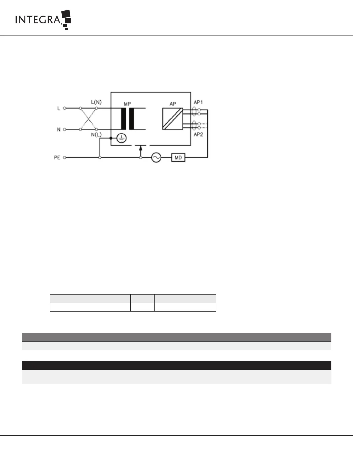
Measurements of Applied Part Leakage Current
(a) TN-System (Direct Method AC)
1. The Safety Analyzer is connected directly to the mains on TN-System
2. Connect the console to the main power socket of the Safety Analyzer.
Figure 7-4
3. Select Applied Part Leakage Current measurement on the safety Analyzer.
4. Turn on the DUT and wait for the GUI to load
5. Connect the handpiece, aspiration, irrigation tubing kit, waste canister, and other accessories to the console and cart.
6. Prime the irrigation tubing and perform a handpiece test.
7. On the DUT main menu, set up the system as follows:
• AMPLITUDE to 100%
• ASPIRATION to 100%
• IRRIGATION to 2ml/min
• TISSUE SELECT to OFF
8. Aached the crocodile clip from the Safety Analyzer lead (Applied Part module port 1) to the proximal end of the tip (without the flue).
Immerse the full tip into a jar feed with 1 liter of water.
9. Press the footswitch Vibrate pedal fully down, to achieve maximum stroke.
10. Obtain the Applied Part Leakage Current measurement, and normalize the value according to Section 7.8.3 Normalization Instructions.
11. Record values in the Electrical Safety Test Datasheet (IT0738A in Appendix A).
 Loading...