Functional Architecture Intel® 5000 Series Chipsets Server Board Family Datasheet
Revision 1.1
Intel order number D38960-004
16
Table 1. DIMM Module Capacities
SDRAM Parts / SDRAM Technology Used 512Mb 1Gb 2Gb 4Gb
X8, single row 512MB 1GB 2GB 4GB
X8, double row 1GB 2GB 4GB 8GB
X4, single row 512MB 1GB 2GB 4GB
X4, Stacked, double row 1GB 2GB 4GB 8GB
DIMMs on channel A are paired with DIMMs on channel B to configure 4-way interleaving. Each
DIMM pair is referred to as a bank. The bank can be further divided into two rows, based on
single-sided or double-sided DIMMs. If both DIMMs in a bank are single-sided, only one row is
said to be present. For double-sided DIMMs, both rows are said to be present.
The server and workstation boards have eight DIMM slots, or four DIMM channels. Both DIMMs
in a channel should be identical (same manufacturer, CAS latency, number of rows, columns
and devices, timing parameters, etc.). Although DIMMs within a channel must be identical, the
BIOS supports various DIMM sizes and configurations, allowing the channels of memory to be
different. Memory sizing and configuration is guaranteed only for qualified DIMMs approved by
Intel.
Note: Some boards vary in memory capacity. See the server or workstation Technical Product
Specification that applies to your product for more information.
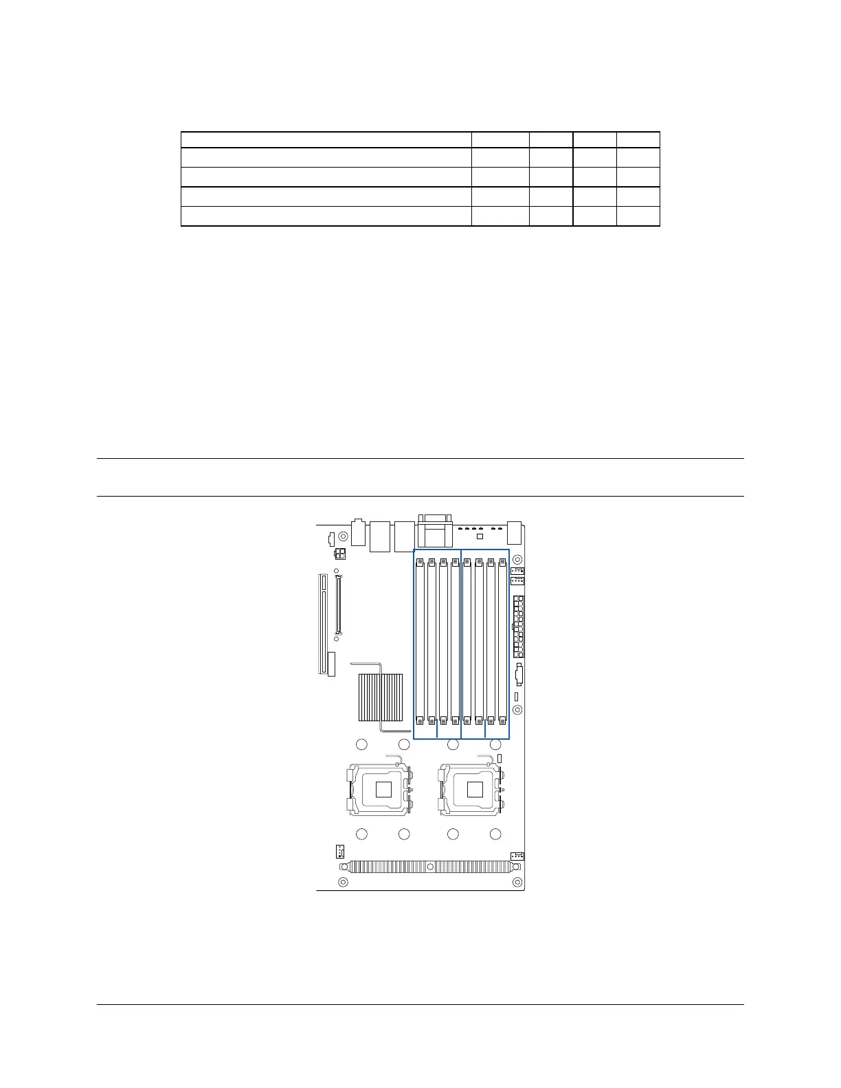
AF000169
Branch 1 Branch 2
Ch 1 Ch 2 Ch 3 Ch 4
DIMM A1
DIMM A2
DIMM B1
DIMM B2
DIMM C1
DIMM C2
DIMM D1
DIMM D2
Figure 4. Identifying Banks of Memory