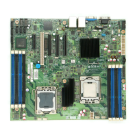
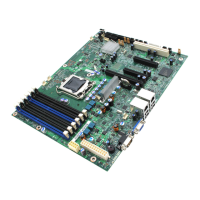
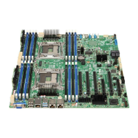
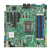
Intel® 5000 Series Chipsets Server Board Family Datasheet Functional Architecture
Revision 1.1
Intel order number D38960-004
11
2.1.2.11 Real-time Clock (RTC)
The Intel
®
631xESB / 632xESB I/O Controller Hub contains a Motorola* MC146818A-compatible
real-time clock with 256 bytes of battery-backed RAM. The real-time clock performs two key
functions: keeping track of the time of day and storing system data, even when the system is
powered down. The RTC operates on a 32.768-KHz crystal and a separate 3-V lithium battery.
The RTC supports two lockable memory ranges. By setting bits in the configuration space, two
8-byte ranges can be locked to read and write accesses. This prevents unauthorized reading of
passwords or other system security information.
2.1.2.12 General-purpose Input/Output (GPIO)
General-purpose inputs and outputs are provided for custom system designs. The number of
inputs and outputs depends on the Intel
®
631xESB / 632xESB I/O Controller Hub configuration.
All unused GPI pins must be pulled high or low, so they are at a predefined level and do not
cause problems.
Note: See the Intel
®
server board or workstation board technical product specification that
applies to your product for more information.
2.1.2.13 System Management Bus (SMBus 2.0)
The Intel
®
631xESB / 632xESB I/O Controller Hub contains a SMBus host interface that allows
the processor to communicate with SMBus slaves. This interface is compatible with most I
2
C
devices. Special I
2
C commands are implemented. The SMBus host controller for the I/O
Controller Hub provides a mechanism for the processor to initiate communications with SMBus
peripherals (slaves).
The Intel
®
631xESB / 632xESB I/O Controller Hub supports slave functionality, including the
Host Notify protocol. The host controller supports eight command protocols of the SMBus
interface: Quick Command, Send Byte, Receive Byte, Write Byte/Word, Read Byte/Word,
Process Call, Block Read/Write, and Host Notify.
See the System Management Bus (SMBus) Specification, Version 2.0 for more information.
2.2 Processor Sub-system
The support circuitry for the processor sub-system consists of the following:
Dual LGA771 zero insertion force (ZIF) processor sockets
Processor host bus AGTL+ support circuitry
Reset configuration logic
Processor module presence detection logic
BSEL detection capabilities
CPU signal level translation
Common enabling kit (CEK) CPU retention support
 Loading...
