Intel Server Board SE7501HG2 Product Guide
50
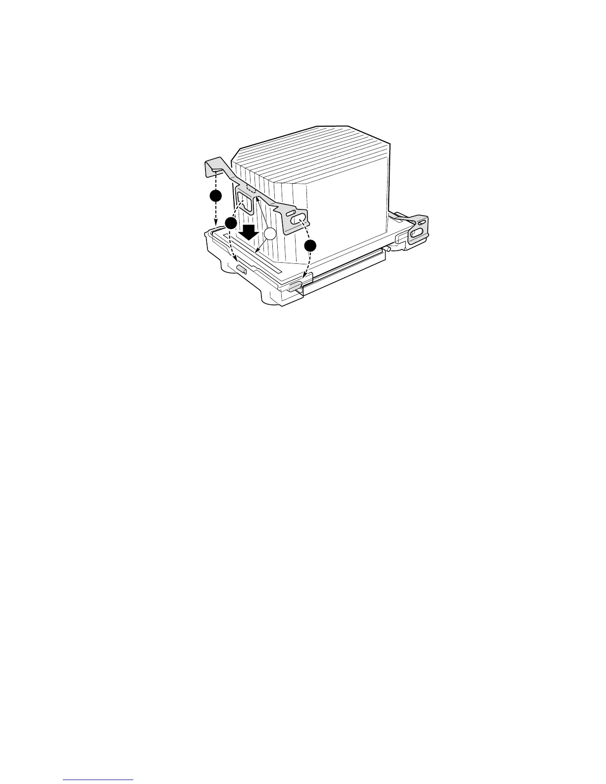
7. Place the heat sink clip (1) so the tab on the clip engages the slot on the heat sink (A).
8. Press one end of the clip down (2).
9. Press the other end of the clip down (3).
OM14140
A
1
2
3
Figure 23. Installing the Heat Sink Clip
Replacing a Processor
1. Observe the safety and ESD precautions at the beginning of this chapter and the additional
cautions given here.
2. Unplug the processor fan cable from the server board.
3. For a chassis in which a PWT assembly is used, detach the fan assembly from the PWT
retention mechanism by unlatching the clips at the bottom of the fan assembly and then lifting
up on the fan assembly.
4. Remove the metal retention clips from the bottom of the retention mechanism. Unhook each
side of each clip and disengage the center latch.
5. Remove the heat sink by slightly spreading the sides of the retention mechanism and lifting
straight up on the heat sink.
6. Raise the socket lever on the processor socket.
7. Remove the processor from the socket.
8. Align the pins of the replacement processor with the socket, and insert the processor into the
socket. Lower the socket lever completely.
✏
NOTE
Make sure the alignment triangle mark and the alignment triangle cutout
align correctly.
9. Re-insert the heat sink over the top of the processor.
10. Reconnect the retention clips. See Figure 12.