53
1. Connection for extension.
2. Connection for handset.
3. Connection for key module.
4. Motion Sensor¹: enables the monitoring of spaces through an infrared sensor installed in the foot of the terminal. After
detecting a movement in the room, the terminal can emit a sound warning, make a call to a predetermined number
(internal or external), send an SMS or trigger an External Action.
5. Connection for headset.
¹ If your product has a motion sensor.
2
To use these services check availability at the PABX.
3
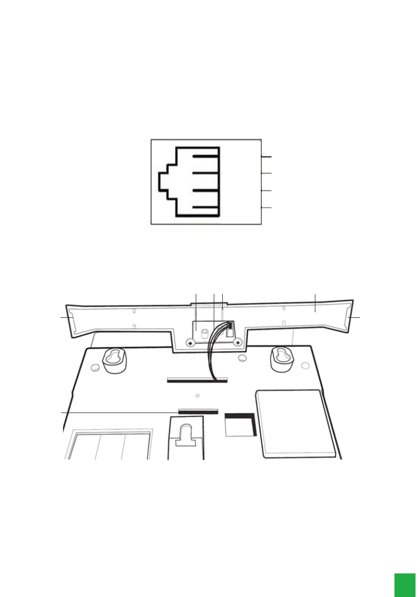
The headset’s pinning must follow the TX-, RX-, RX+ and TX+ standard, as shown in the following image:
1
2
3
4
-TX
+TX
Headset
+RX
-RX
Headset Pinning
3.2. Assembling the base
55
2
4
513
1. Connection cable between the TI 5000 board and the motion sensor¹.
2. Foot of the terminal.
3. Motion sensor board.
4. Base hooking.
5. Left side foot lock, center foot lock, and right side foot lock.
¹ If your product has a motion sensor.
Assembling the TI’s foot
First insert the central lock of the foot into the terminal, then insert the lateral locks in the terminal, if any lock of the foot
is not inserted in the terminal base, you can exert a force on the side of the foot that is not yet inserted or, please repeat
the process from the rst step instructed.