95
Combo Drive (MESAM86)
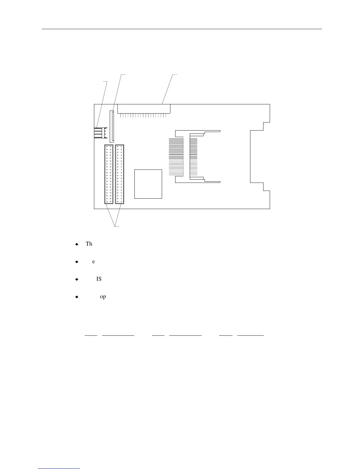
The following figure shows the cable connectors on the combo drive.
Converter
Connector
Floppy
Connector
J2
J5 J4
J6 J3
Power
Connector
ISA Bus
Connectors
u
The power connector uses MCBL086A power cable from the power distribution board. Refer to
the table “J2, MCBL086A, Combo Drive Power” on page 73 for the cable pinout.
u
The ISA bus connector J3 uses MCBL084A and connects to J28 on the system board. Refer to the
table “J28, MCBL084A, PCMCIA ISA Bus” on page 63 for the cable pinout.
u
The ISA bus connector J6 uses MCBL084A and connects to J27 on the system board. Refer to the
table “J27, MCBL084A, PCMCIA ISA Bus” on page 63 for the cable pinout.
u
The floppy connector uses cable MCBL106A and connects to J29 on the I/O expansion board.
Refer to the table “J29, MCBL106A, Floppy” on page 64 for the cable pinout. The floppy
connector also uses cable MCBLZ230 to connect to the converter connector J4 on the combo
drive. The following table shows the pinout of MCBLZ230.
Pin
Signal Pin Signal Pin Signal
1 VCC 10 MTR1- 19 Ground
2 INDEX- 11 No connect 20 TRK0-
3 VCC 12 DIR 21 Ground
4 DRV1- 13 No connect 22 WRPRT-
5 VCC 14 STEP- 23 Ground
6 DSKCHG 15 Ground 24 RDATA-
7 No connect 16 WDATA- 25 Ground
8 No connect 17 Ground 26 HDSEL
9 RPM 18 WGATE-