90
Intruder Alert
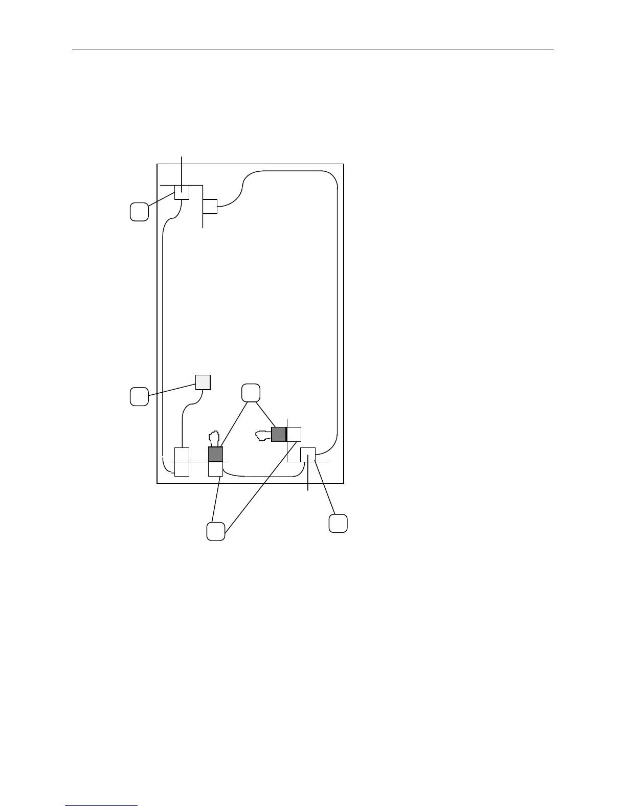
The 19-inch rack is wired to report intruder alerts to InterServe 650 and 660 systems in the rack or in
adjacent racks. The following diagram illustrates the wiring scheme:
1. Front Door Switch - This switch is closed
when the door is closed. When opened,
the intruder alert activtes, if configured to
do so in the LCD menu. Refer to Chapter
3 of the
System Setup
.
2. Expansion Plugs - These plugs are loop
access points, which provide connection to
expansion racks. Terminators (3) are
installed to close the circuit if expansion
racks are not connected.
3. Terminators - These items close the
circuit loop, and are removed to
accomodate intruder alert cabling for
expansion racks.
4. Rear Door Switch- This switch is closed
when the door is closed. When opened,
the intruder alert activtes, if configured to
do so in the LCD menu. Refer to Chapter
3 of the
System Setup
.
5. Connector - The connector at the end of
the intruder alert cable attaches to the
base unit, and detects an open circuit.
Front of System Rack
1
5
4
3
2