Advisor Advanced ATSx000A(-IP) Installation and Programming Manual 15
Zone connection
The inputs are set up as standard EOL freely programmable zones. However, by
programming the zones as dual loop, all zone inputs can be programmed to give
a few states indication for the same zone.
Depending on the detector model, do the following to set up zones:
• Choose your EOL connection type. See “EOL connection types” on page 19.
• Program input mode. See “8.5.1 Input mode” on page 152 for the panel, or
“2.2.2.n.4.4 Input mode” on page 76 for expanders.
• Set end-of-line resistor values. See “8.5.2 EOL” on page 152 for the panel, or
“2.2.2.n.4.5 EOL” on page 76 for expanders.
• Configure anti-masking option. See “4.1.n.6.6 Anti mask” on page 98.
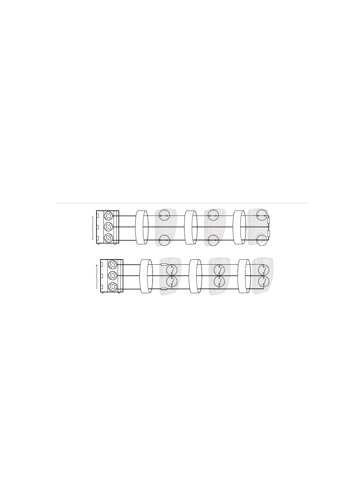
Single loop zone wiring
In single loop zone wiring, two zones are required, one zone for alarm and one
zone for tamper. The tamper contacts are wired in series with an EOL resistor.
Figure 15: Single loop examples
(1) Zone terminal
C Common terminal
Z1 Zone 1 input
Z2 Zone 2 input
(2) Detector
A Alarm relay
T Tamper relay
Dual loop zone wiring
In dual loop wiring, one zone can detect a few detector states. At least two
resistors are used to define alarm and tamper states. Depending on the
programmed settings, there can be additional states defined as masking alarm or
sensor fault. These states can be the following:
• Short (tamper)
• Active (alarm)
• Normal
• Masking
• Sensor fault
• Open (tamper)
C
(1)
T
()2
RA
Z2Z1
A A A
T T
RT
()2 ()2
C
(1)
A
T
()2
RA
Z2Z1
RT
()2 ()2
A
T
A
T