Chapter 4 — Interfaces
EasyCoder PD41/PD42 Printer Service Manual 87
One line contains +5 VDC, max 500 mA, permanently enabled.
Installing the Parallel IEEE1284 Interface
The installation kit contains:
• Parallel IEEE1284 interface board with I/O bus cable.
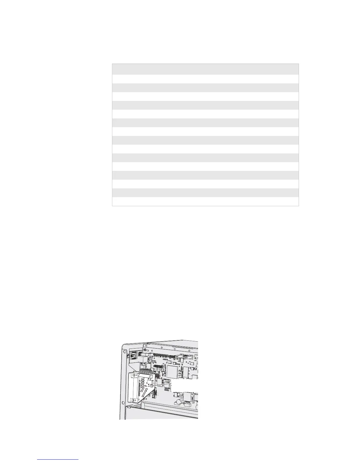
To install the Parallel IEEE1284 option
1 Disconnect the power cord and remove the left-hand panel (For help,
see “To remove the left-hand panel” on page 27).
2 Put the printer back in upright position.
3 Remove the small plate that covers the slot for the Parallel board on the
back of the printer. Keep the screws.
4 Use the screws that were removed in Step 3 to secure the Parallel board
in the slot.
Signals
Pin Function Transmitter Comment
1/Strobe host
2-9 Data 0-7 host
10 /Acknowledge printer
11 Busy printer
12 /Paper empty printer
13 /Select printer
14-15 Not connected
16 Logic ground
17 Chassis ground
18 External +5 VDC Max 0.5A, permanently enabled.
19-30 Signal ground
31 Not connected
32 /ERROR printer
33 Signal ground
34-36 Not connected
Parallel IEEE 1284
interface board