Chapter 3 — Replacing Parts
EasyCoder PD41/PD42 Printer Service Manual 21
Front Panel (PD42)
The EasyCoder PD42 has a front panel molding with a LCD, four colored
LED control lamps and a Print button.
The control lamp LEDs are fitted on a console PCB that also contains the
switch for the print button. An overlay, covered with a transparent plastic
window, provides the icons for the LEDs. The console PCB is connected to
connector P92 (“CONSOLE”) on the main board via a separate flat cable.
Another flat cable runs from the display to the connector P46 (“LCD”) on
the main board. The Label Taken Sensor uses a separate cable which
connects to connector P38 (“LTS”), also on the main board.
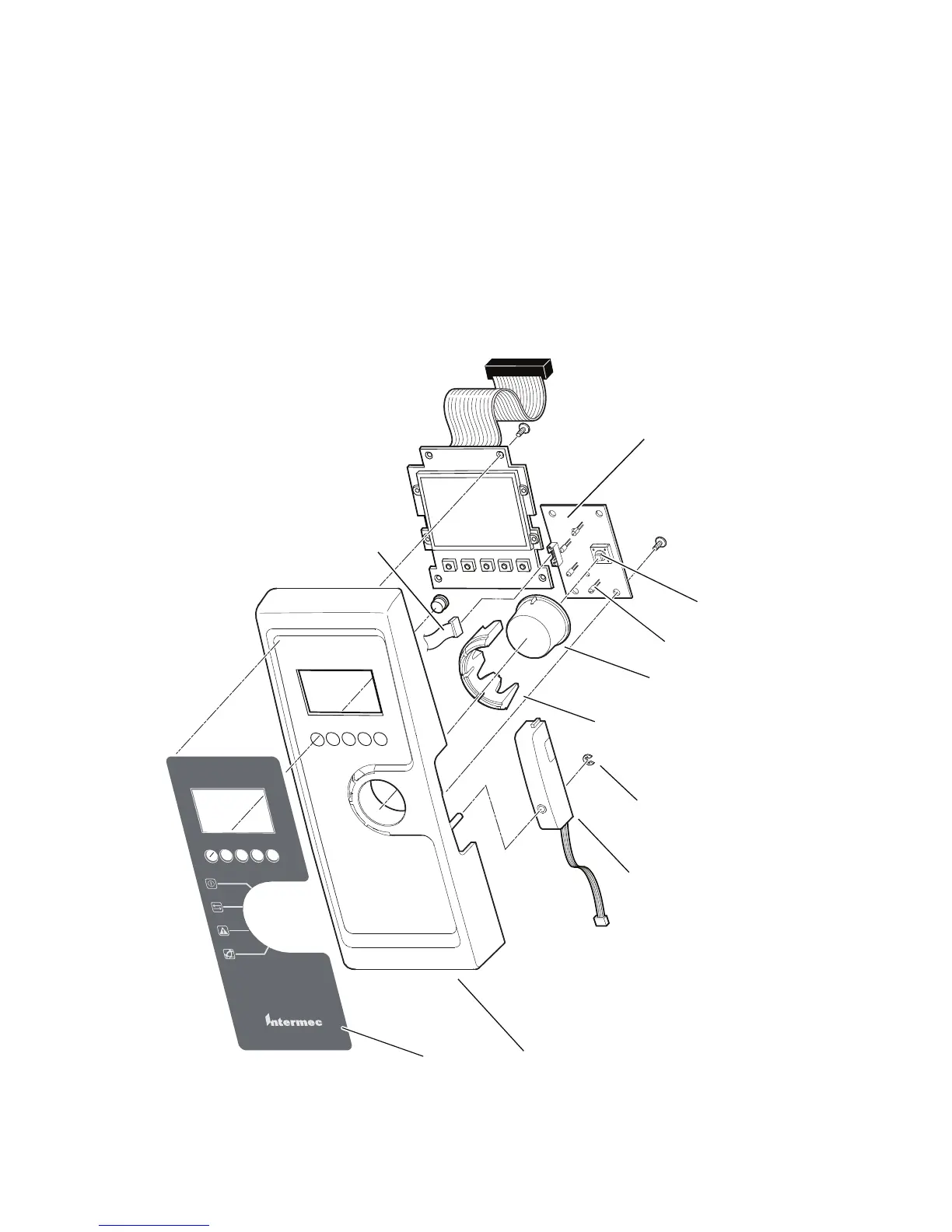
PD42 Front Panel: Exploded View
Screw
(4 places)
Screw
(4 places)
EasyCoder PD42
Overlay
Front Panel
Label Taken Sensor
Print button switch
LEDs (green-green-red-blue)
Print button
Light guide
E-ring
Console PCB
Flat cable to
main board