IPETRONIK PlugIn X V02.14.00
Both settings support incremental sensors that provide a second phase-shifted output signal used for
detection of the rotation direction. This can be used for positive / negative frequency / rpm indication or as up
& down counter.
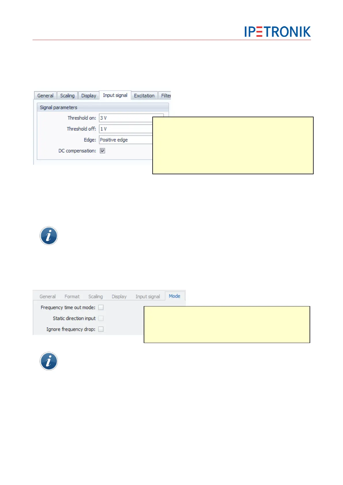
Input signal
An oscilloscope is recommended for displaying the signal behavior for configuring the switching thresholds
on and off. If the sensor signal does not exceed the threshold on or fall below the threshold off, no exact
acquisition is possible. In this case, the value does not change although the revolutions per minute increase
and the sensor is connected correctly. Correct the threshold values in the configuration and run a test
acquisition.
Please note that a lot of speed sensors send an almost ideal square wave signal in the lower
frequency range, but the graph changes with increasing frequency (> saw tooth). This can also
be caused by external capacities e.g. a (long) connection cable to the sensor.
Mode (M-CNT2)
Mode Frequency with/without direction
If the Frequency time out mode is activated, the maximum gate time of 42 s is set in the Input
signal tab. This enables frequency measurement down to 0.0238 Hz, while lower frequencies
will be output as 0 Hz. In order to indicate a rotation stop immediately, a short gate time is
recommended, but this means, the minimum frequency that can be measured increases.
Example Input signal tab > Zero detection threshold:
Gate time: 0.5 s > minimum frequency that can be measured: 2 Hz (correlating to 120 rpm)
Input signal
1. Select the upper threshold with Threshold on in a range of +/-40 V.
2. Select the lower threshold with Threshold off in a range of +/-40 V.
The lower threshold must always smaller than the upper one.
3. Select an edge for defining the positive or negative signal edge. If
the negative edge is selected, the input signal will be inverted.
4. The DC compensation disables the direct current component in the
signal with a passive high-pass (1-pole, 0.8 Hz cut-off frequency).
Frequency time out mode Fixed gate time setting to 42 s
Static direction input 2nd signal used with input 2 resp. input 4 to
define the direction of rotation.
(for example: level high means right hand
rotation, level low means left hand rotation)