4210 Flow Meter
Section 4 Optional Equipment
4-7
• Use a larger battery: either a commercial
deep-cycle/marine type, or an Isco 35 Ampere-hour
lead-acid battery.
• Order and use only one analog output.
• Flow meter program choices also affect power
consumption. Use “minimum” settings, if possible. (See
Section 1, Table 1-4.)
The outputs from the analog output board are electrically iso-
lated from the flow meter and from each other by internal
DC-DC converters. The board uses the opening for the modem
connector for its outputs. Normally, a flow meter will not need
both the analog and modem boards. If your installation does,
however, you should contact the factory.
The analog board terminates in a 6-pin male M/S connector on
the flow meter case. Flow meters built with the analog board
option are also supplied with an output cable. This cable con-
nects to the wiring that runs to the equipment controlled by the
4-20 mA current loop and to the 6-pin M/S connector on the flow
meter. The cable has a 6-pin female M/S connector and is pro-
vided with stripped pigtail ends for convenient wiring.
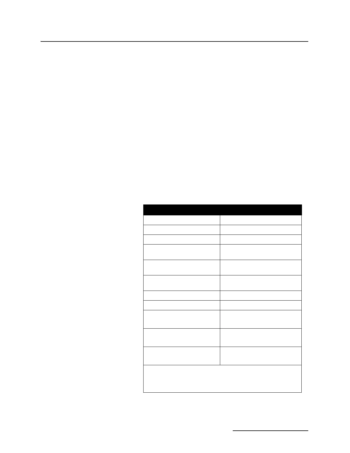
Table 4-2 Internal 4-20 mA Specifications
Temperature (operating) 0 to 140° F (–18 to 60° C)
Output Accuracy
±0.5% of full-scale
Resolution 0.1% of full-scale (0-20 mA)
Electrical Isolation Isolated from each other and from
the flow meter.
Calibration Factory-calibrated; no further
adjustments necessary.
Maximum output distance 1500 feet (457.3 m) using 18 AWG
wire.
Current Range (per loop) 0 to 20 mA
Maximum Load (per loop) 750 ohms
Analog Output 1 Terminations Pin A (Red wire –)
Pin C (White wire +)
Analog Output 2 Terminations Pin D (Brown wire –)
Pin F (Blue wire +)
Analog Output 3 Terminations Pin E (Black wire –)
Pin B (Green wire +)
Note: If you must strip the cable further back to facili-
tate wiring, you will expose an orange, yellow, and
purple wire. You may disregard these wires, as they
are not connected in this application.