4210 Flow Meter
Section 5 Maintenance and Service
5-10
5.4 Servicing and
Troubleshooting
This section of the 4210 instruction manual provides servicing
information and a troubleshooting guide to assist you in cor-
recting certain minor malfunctions that might occur. Included
are sections describing disassembly of the unit, on fuse
replacement, and on the care and repair of CMOS circuitry.
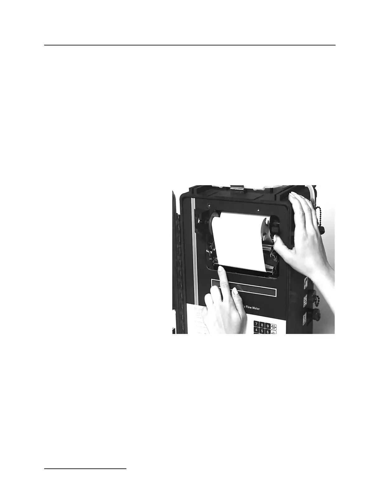
You can remove the flow meter mechanical assembly from the
cabinet for inspection and servicing, if necessary. First, remove
the four screws, two at the top, and two at the bottom, that hold
the flow meter chassis in the cabinet. Then you can lift chassis
out by carefully inserting the thumb or index finger from each
hand into the upper right and lower left corners of the opening
surrounding the printer. Do not try to lift the flow meter out of
the case by holding on to any part of the printer. If you do, you
could bend or distort part of the printer, possibly damaging it.
Once the chassis has cleared the case, you can grip it with both
hands by its edges and lift it free of the case.
Figure 5-6 Lifting the Flow Meter from the Cabinet
5.4.1 Fuse Replacement With the flow meter chassis out of the cabinet, you can locate and
change fuses. The fuses are located on the printed circuit board
under a cover on the back of the flow meter keyboard assembly.
Slide the cover off and you can see the fuses. The fuses are
labeled F1, F2, and F3. The proper size for each of these fuses is:
F1 - 5 amp., fast blow
F2 - 5 amp., fast blow
F3 - 2 amp., fast blow
Always replace a blown fuse with one of the same value. Using a
larger value fuse may cause serious damage to the flow meter or
to its power supply.