16
DAILY MCA2014 4x4 ‒ BODYBUILDER INSTRUCTIONS
ELECTRONIC SUB-SYSTEMS
5.2 BODYBUILDER CONNECTORS
– Printed 603.95.994 – 1 Ed. - Base 05/2015
230830
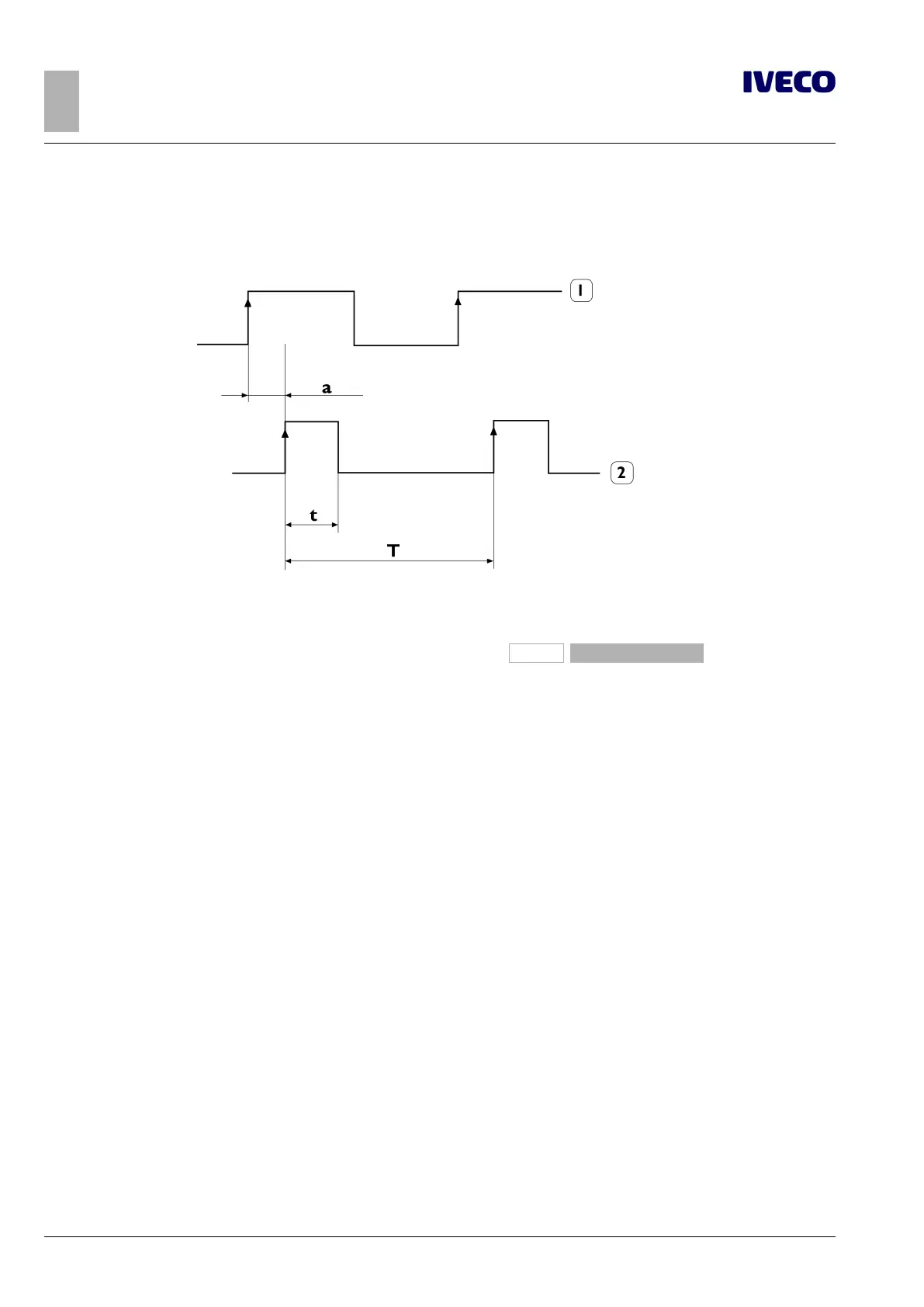
Figure 13
1. Speed signal (terminal B3) of the movement sensor fitted
on the reduction unit
2. Temporal diagram and form of the pulse speed signal
(terminal B7) from tachograph
a. Pulse delay: max 40 μs
±
10 μs jitter
(4)
WARNING:
If the K15 Remote control was activated and the operator removed the ignition key with the engine running, the en-
gine would not stop and it would be possible to move the vehicle with the steering locked. Therefore:
● The K15 Remote control must not be activated with the engine running.
● Similarly, to avoid unexpected movements of the vehicle with gear engaged, the engine must not be running when
the K15 Remote control is activated.
If, in spite of such requirements, engine operation must still be possible, IVECO recommends using the RunLock function offered by the Ex-
pansion Module (if present): please consult the specific manual EM 603.95.826 (currently being updated at the time of publication of the
present document).
(5)
Rpm signal
The rpm signal is a square wave.
The characteristics of the rpm signal are:
● 4 pulses for each revolution of the crankshaft;
● frequency field 0 ÷ 400 Hz (corresponding to 0÷6000 revs/min);
● duty-cycle fixed at 50%.

 Loading...
