36
DAILY MCA2014 4x4 ‒ BODYBUILDER INSTRUCTIONS
ELECTRONIC SUB-SYSTEMS
5.4 ELECTRICAL SYSTEM: CURRENT INTERVENTIONS AND DRAWS
– Printed 603.95.994 – 1 Ed. - Base 05/2015
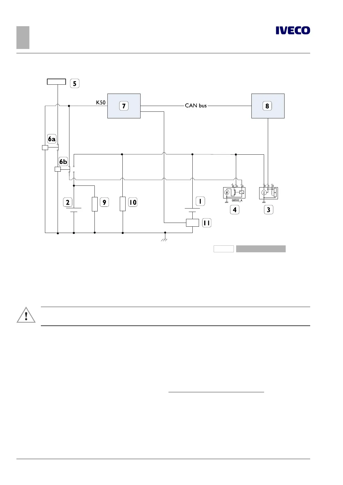
208936
Figure 34
1. Standard battery
2. Additional batteries
3. Alternator with built-in regulator
4. Starter motor
5. Ignition switch
6. Contactor switches
7. Body Computer
8. Engine Management control unit
9. Auxiliary load
10. Vehicle load
11. LIN bus
▶ All the lines downstream of all batteries are to be adequately protected, under any fault condi-
tion. Failure to ensure adequate protection may pose a fire hazard and a danger to persons.
Additional alternators
The NEW DAILY 4x4 is equipped with an advanced “smart” alternator controlled by the engine ECU.
This alternator is capable of delivering electrical current only when it is really necessary, and is able to always guarantee a correct
state of battery charge through the sensor on the negative pole.
In cases where there are very onerous electrical loads a second alternator may be used, and it must be installed (with all the mech-
anical requirements necessary for compatibility with the vehicle and under the responsibility of the bodybuilder) according to the
diagram in Figure 35.
The additional alternator must be of the traditional type, with pin L connected in order to ensure excitation with a current
between 150 and 200 mA. The diagnostic light is optional, but a resistance is still necessary to ensure excitation.
Dual alternator operation requires that the additional traditional alternator is the one that delivers in any condition (as it is not con-
trolled), while the original "smart" alternator intervenes when the electrical balance becomes negative (the battery charge status is
monitored)

 Loading...
