DAILY MCA2014 4x4 ‒ BODYBUILDER INSTRUCTIONS
ELECTRONIC SUB-SYSTEMS
5.4 ELECTRICAL SYSTEM: CURRENT INTERVENTIONS AND DRAWS
37
– Printed 603.95.994 – 1 Ed. - Base 05/2015
The diagnosis of the two alternators is ensured by:
● a battery indicator on the instrument panel, with regard to the first alternator
● an external diagnostic light (if installed) for the additional alternator
208950
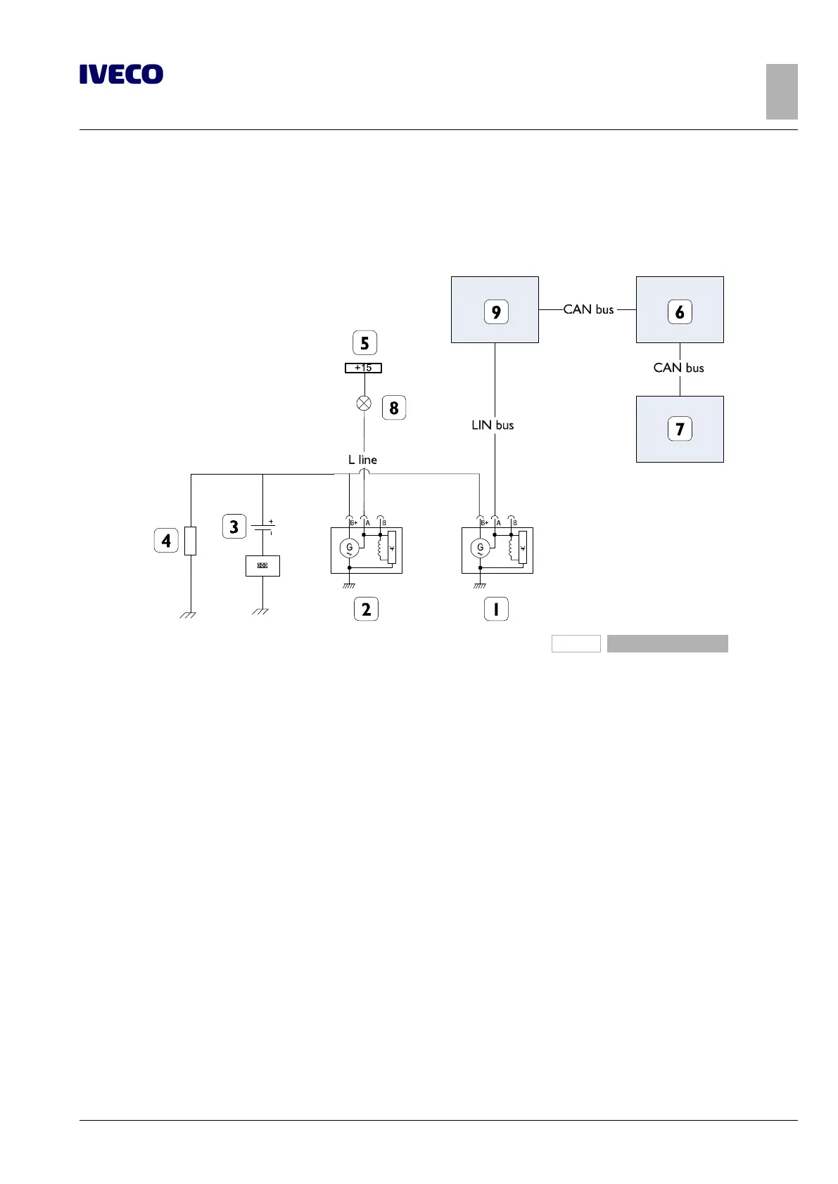
Figure 35
1. "Smart" first use alternator
2. Additional standard alternator
3. Battery
4. Electrical loads
5. Signal +15 from ignition switch
6. Body Computer
7. Instrument panel
8. Diagnostics Lamp or LED +Res. (current between 150
and 200 mA)
9. Engine Management control unit
The installation of additional equipment must include suitable protections and should not overload the vehicle system.
The additional alternators must be the type with Zener diode rectifiers to avoid damaging electric/electronic equipment due to
accidental battery disengagement. Each alternator must also have a light or LED indicating low battery charge.
The additional alternator must have electrical features identical to those of the standard alternator and the cables must be correctly
sized.
If you need to modify the system in a way other than described in this manual (for example, adding batteries in parallel), it is neces-
sary to share the operation with IVECO.

 Loading...
