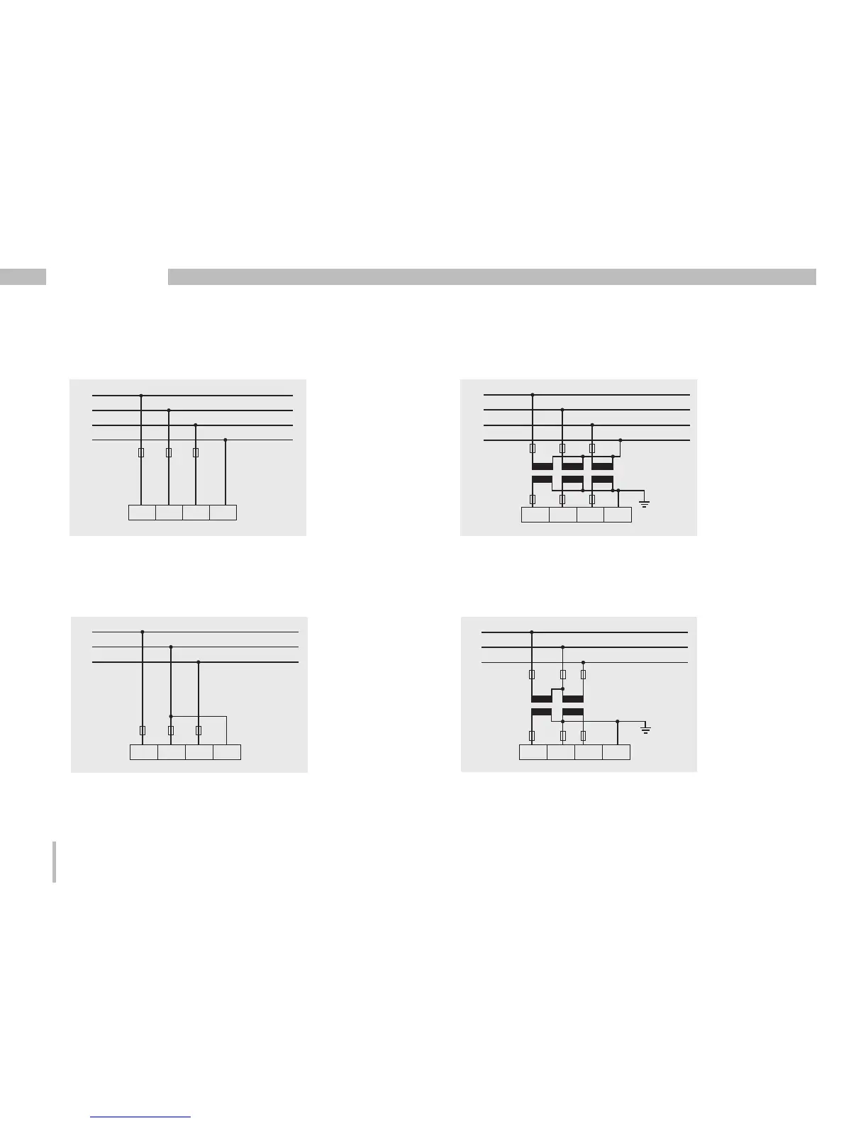
Wiring diagrams, voltage measurement
L1
L2
L3
N
V1 V2 V3 VN
• 3p 4w (Addr. 509= 0), factory setting
L1
L2
L3
N
V1 V2 V3 VN
• 3p 4wu (Addr. 509 = 1)
• 3p 4u (Addr. 509 = 2)
L1
L2
L3
V1 V2 V3 VN
L1
L2
L3
V1 V2 V3 VN
• 3p 2u (Addr. 509 = 5)
Fig. System with three line conductors
and neutral conductor.
Fig. System with three line conductors
and neutral conductor. Measurement using
a voltage transformer.
Fig. System with three line conductors without
neutral conductor. Measurements which require
a N are based on a calculated N.
Fig. System with three line conductors without
neutral conductor. Measurement using a voltage
transformer. Measurements which require a N
are based on a calculated N.