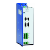
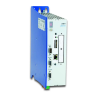
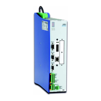
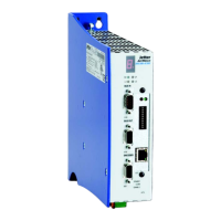
10 Connection Diagrams
90 Jetter AG
Key to wiring diagrams:
1 Line filter (optional) (refer to “Line filter" on page 39)
2 Mains protection (refer to “Overload Protection" on page 38)
3 Motor
4 Motor holding brake (option)
5 – Connecting without the option -S1 (Safe Torque Off): The
input for enable is connected in single-channel mode.
– Connecting with the option -S1 (Safe Torque Off): Enable1
and Enable2 are connected in dual-channel mode.
6 The motor holding brake is controlled via an internal
semiconductor-switch. A free-wheeling diode has been
integrated.
7 To use initiators for end position and reference inputs, a 24 V
power supply unit and a 0 V ground have been made available
as terminals.
8 Position transducer (resolver or HIPERFACE encoder)
9 Motor-temperature protection (see “Thermal sensor integrated
in the motor" on page 43)
10 At using the option -JC24x, the Bus-In connector X18 must not
be applied, as the system bus is connected with the JM-D203
internally.