SECTION 5 - BASIC HYDRAULIC INFORMATION & SCHEMATICS
5-124 3121714
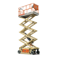
2. Use a soft mallet to tap a new wiper seal into the appli-
cable cylinder head gland groove.
3. Place a new o-ring and backup seal in the applicable
outside diameter groove of the cylinder head.
4. Place the cylinder cap over the rod and carefully install
the head gland on the rod, ensuring that the wiper and
rod seals are not damaged or dislodged. Push the head
along the rod to the rod end.
5. Push the spacer onto the rod.
6. Place a new o-ring in the inner piston diameter groove.
7. Using suitable protection, clamp the cylinder rod in a
vise or similar holding fixture as close to piston as possi-
ble.
8. Carefully thread the piston on the cylinder rod hand
tight, ensuring that the o-ring are not damaged or dis-
lodged.
9. Thread piston onto rod until it abuts the spacer end and
install the retainer.
10. Remove the cylinder rod from the holding fixture.
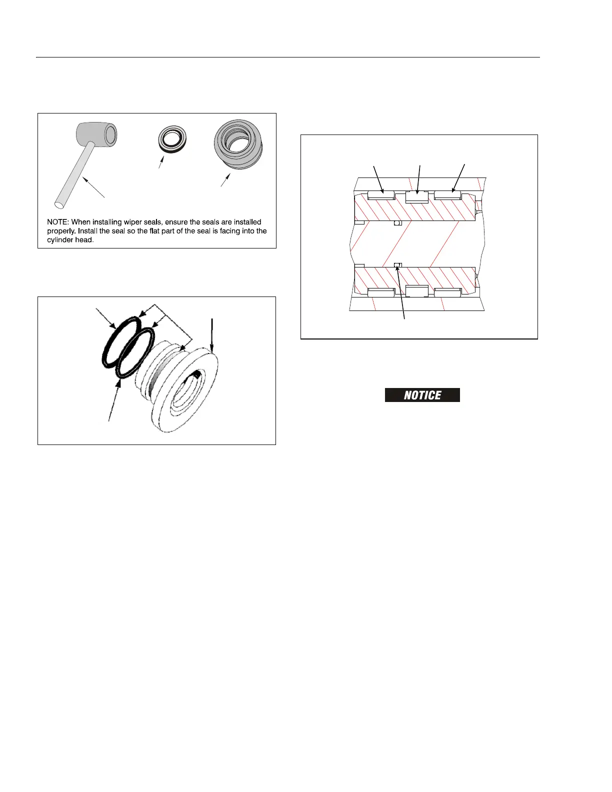
11. Place new cap seal and wear rings in the outer piston
diameter groove. (A tube, with I.D. slightly larger than
the O.D. of the piston is recommended to install the
solid seal).
12. Position the cylinder barrel in a suitable holding fixture.
EXTREME CARE SHOULD BE TAKEN WHEN INSTALLING THE CYLINDER ROD,
HEAD, AND PISTON. AVOID PULLING THE ROD OFF-CENTER, WHICH COULD
CAUSE DAMAGE TO THE PISTON AND CYLINDER BARREL SURFACES.
13. With barrel clamped securely, and while adequately sup-
porting the rod, insert the piston end into the barrel cyl-
inder. Ensure that the piston loading o-ring and seal ring
are not damaged or dislodged.
14. Continue pushing the rod into the barrel until the cylin-
der head gland can be inserted into the barrel cylinder.
15. Install cylinder head as mention below:
a. Secure the cylinder head gland and the cylinder
cap. Refer Figure 5-133.
b. Screw the cylinder head into the barrel using a
pin-face spanner wrench. Refer Figure 5-134.
16. After the cylinder has been reassembled, the rod should
be pushed all the way in (fully retracted) prior to the re-
installation of any holding valve or valves.
17. Install the counterbalance valves in the rod port block.
18. Install wear pad onto the cylinder.
Figure 5-138. Wiper Seal Installation
8*1&3
4&"-
$:-*/%&3
)&"%
."--&5
Figure 5-139. Installation of Head Seal Kit
&</,1'(5
+($'
%$&.83
5,1*
25,1*
WEAR
RING
O-RING
WEAR
RING
CAP SEAL
Figure 5-140. Piston Seal Kit Installation
 Loading...