SECTION 3 - CHASSIS & TURNTABLE
3121714 3-5
3.3 TILT MODULE
When installing a new tilt module, always ensure that it is cali-
brated using the JLG Control System analyzer before operating
the machine. Refer to Section 6, JLG Control System Analyzer
Kit Instructions. Use a standard bubble level in two different
directions to ensure that the machine’s frame is level prior to
installing the new tilt module.
1. Place the machine on a flat, level surface. Check for level
by placing a bubble level on the frame in both direc-
tions.
2. Plug in the analyzer (Analyzer - PN 1600244,
Cable - PN 1600633) into port J9 on the power module
or port J1 on the platform module.
3. Use the right arrow key to curse over to “ACCESSLEVEL
2". Depress Enter.
4. Use Up/Down arrow keys to enter the following pass-
word “33271”. Depress Enter.
5. Use the right arrow to curse over to “LEVEL VEHICLE”.
Depress Enter. Depress Enter again.
6. Verify that the tilt reading is now “0.0: 0.0".
TO ASSURE PROPER OPERATION, THE MACHINE MUST BE LEVEL WHEN
INSTALLING AND CALIBRATING A NEW TILT MODULE.
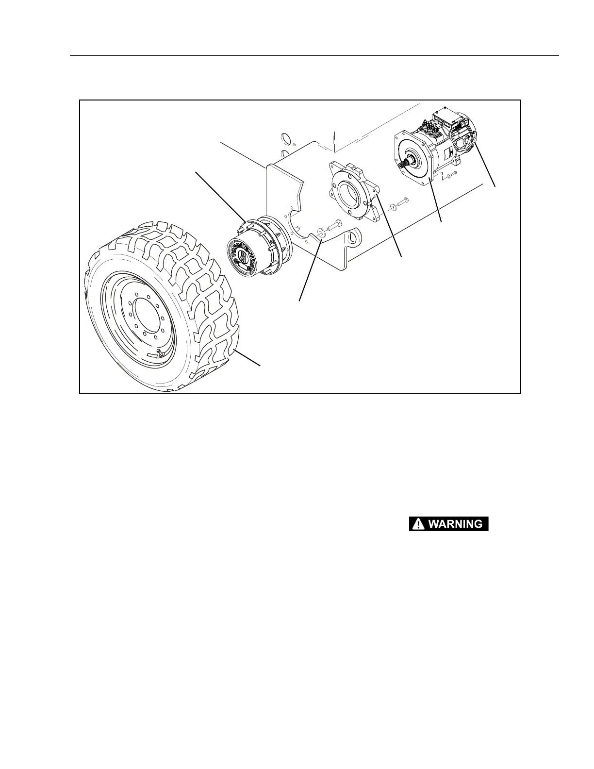
Figure 3-3. Drive Components
MAE38660
TIRE AND WHEEL ASSEMBLY
Apply JLG Threadlocker PN 0100011
Torque to 165 ft. lbs. (224 Nm)
MOTOR ADAPTER
Apply Pipe Sealant
Loctite #567
DRIVE
MOTOR
DRIVE
BRAKE
DRIVE
HUB
NOTE: Torque Wheel Lugs to
170 ft.lbs. (230 Nm)