SECTION 3 - CHASSIS & TURNTABLE
3-64 – JLG Lift – 3121813
engine. The signal is also used in determining if the air
glow plug should be energized.
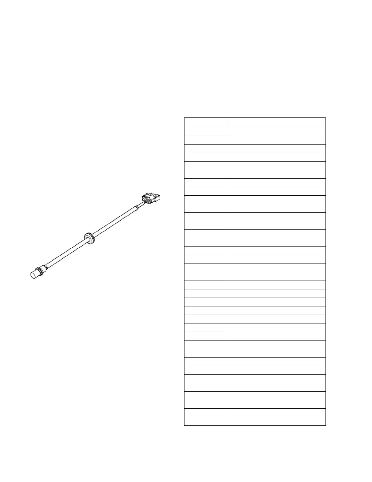
The engine oil temperature sensor is connected to the
engine/generator controller at pins J2-8 and J2-19.
The engine oil temperature sensor is located on the left
side of the engine.
Alternator Output Current Sensor
The alternator output current sensor provides a signal pro-
portional to the output current of the alternator to the
engine/generator controller. The output current is regu-
lated at 45ADC.
The alternator output current sensor is connected to the
engine/generator controller at pins J2-21, J2-31 and J2-
32.
The alternator output current sensor is located inside the
rear cover of the alternator.
Engine Speed Sensor
The engine speed sensor provides a signal proportional
to the rotational speed of the engine to the engine/genera-
tor controller. This signal is used by the engine/generator
controller to determine starter cut-out, overspeed fault and
underspeed fault. If the signal is not present at the engine/
generator controller, the unit will fault with a loss of speed
signal indication.
The engine speed sensor is connected to the engine/gen-
erator controller at pins J2-9, J2-15 and J2-20.
The engine speed sensor is located inside the recoil
starter cover at the front of the engine.
RBS Engine/Generator Controller
The control system enclosure houses the RBS engine/
generator controller, which performs all control tasks
associated with the RBS.
The engine/generator controller interface is via a J2 35-pin
connector.
Table 3-7. Controller Interface Pin Assignments
PIN FUNCTION
1 System 48VDC
2 System 0V DC
3 Fuel solenoid
4Starter Solenoid
5 Manual call to start
6Low oil pressure
7Not used
8 Engine oil temperature
9 Speed sensing input
10 RS-232 +12V
11 RXD
12 TXD
13 LED Driver GND
14 LED Driver +48V
15 Speed sensor GND
16 Not used
17 Not used
18 - Output voltage
19 Engine oil temperature/ambient temp. + 8V
20 Speed Sensing + 8V
21 Output current sensor (GND)
22 Not used
23 RS-232 GND
24 - Field drive
25 + Start battery
26 - Start battery
27 Pre-heat
28 Inhibit run
29 Engine temp. switch
30 + Output voltage
31 Speed sensing + 5V
32 Output current sense
33 Not used
34 Not used
35 Field Drive


 To Next Page