SECTION 3 - CHASSIS & TURNTABLE
3121813 – JLG Lift – 3-55
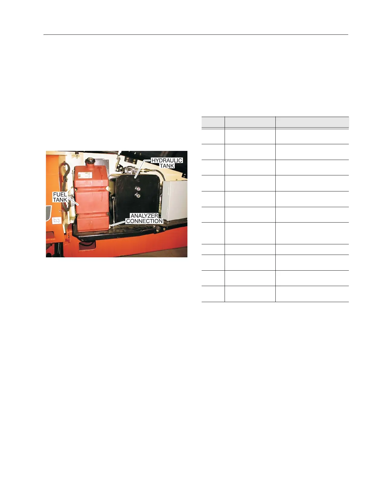
To Connect the JLG Control System Analyzer
to the Generator
The JLG Control System Analyzer can be used to monitor
generator settings and conditions. Connect the analyzer
as follows:
1. Connect the four pin end of the cable supplied with
the analyzer, to the connector behind the ground
control module located on the left side of the
machine next to the ground control station and con-
nect the remaining end of the cable to the analyzer.
The ground control module contains the settings for
the generator.
NOTE: The cable has a four pin connector at each end of
the cable; the cable cannot be connected back-
wards.
2. Power up the Analyzer by pulling out the ground sta-
tion EMS and positioning the Generator Enable
switch on the platform control box to the "on" posi-
tion. Refer to Figure 3-34., Generator System Ana-
lyzer Flow Chart
Alarms and Fault Flash Codes
In the event of an RBS alarm, a flash code will be issued
and an alarm indicated on the analyzer.
NOTE: Alarms must be reset once the fault has been cor-
rected.
•Low Oil Pressure
Enabled once TDBP (time delay bypass) period has
elapsed after engine startup. If the low engine oil pressure
switch closes, the engine will stop immediately and a low
oil pressure alarm will be indicated.
•High Engine Temperature
If the engine oil temperature exceeds the high engine tem-
perature setting, the engine will stop immediately and a
low oil pressure alarm will be indicated.
• Overspeed
If the engine speed exceeds the overspeed limit, the
engine will stop immediately and an overspeed alarm will
be indicated.
Table 3-6. Generator System Flash Codes
Code Alarm Description
1-1
Low Oil Pressure Shutdown due to low engine
oil pressure
1-2
High Engine Tem-
perature
Shutdown due to high engine
oil temperature
1-3
Engine Overspeed Shutdown due to high engine
speed
1-4
Engine Under-
speed/Overcrank
Shutdown due to engine
overcrank or underspeed
1-5
No Speed Signal S hu tdo wn d ue t o l oss of
speed signal
2-1
Overvoltage Shutdown due to high output
voltage
2-2
Engine Starting
System fault
Alarm not a shutdown; Indi-
cates problem with the
engine starting system
2-3
Not Used Not Used
2-4
Loss of Voltage
Sense
Shutdown due to loss of volt-
age sensing
Contin-
uous
Unit Disabled No Faults. RBS enabled and
can respond to any CTS
Off
Unit Disabled RBS off or disabled; Will not
respond to any CTS