SECTION 4 - BOOM & PLATFORM
3121813 – JLG Lift – 4-31
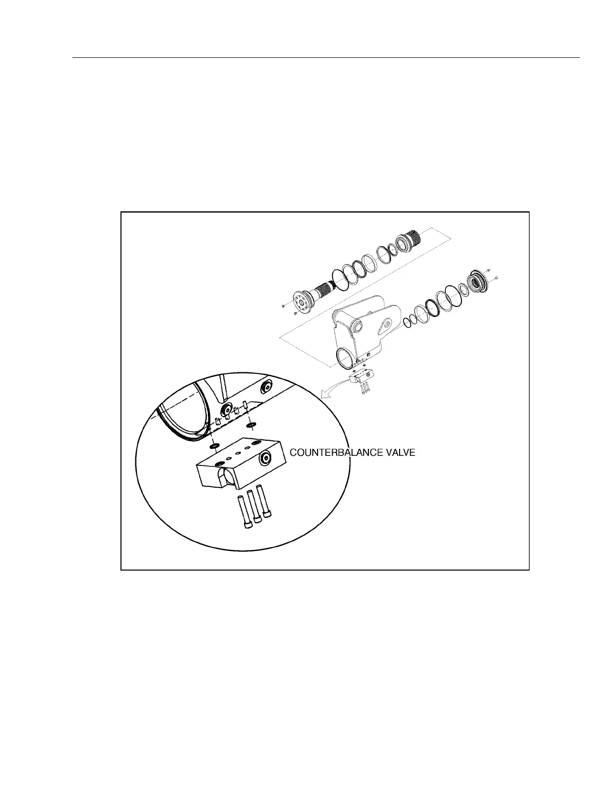
Installing Counterbalance Valve
Refer to Figure 4-14., Rotator Counterbalance Valve.
1. Make sure the surface of the actuator is clean, free
of any contamination and foreign debris including
old Loctite.
2. Make sure the new valve has the O-rings in the
counterbores of the valve to seal it to the actuator
housing.
3. The bolts that come with the valve are grade 8 bolts.
New bolts should be installed with a new valve. Loc-
tite #242 should be applied to the shank of the three
bolts at the time of installation.
4. Torque the 1/4-inch bolts 110 to 120 inch pounds
(12.4 to 13.5 Nm). Do not torque over 125 inch
pounds (14.1 Nm). Torque the 5/16-inch bolts 140
inch pounds (15.8 Nm). Do not torque over 145 inch
pounds (16.3 Nm).
Figure 4-14. Rotator Counterbalance Valve