SECTION 4 - BOOM & PLATFORM
4-26 – JLG Lift – 3121813
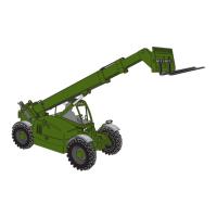
turning in a counterclockwise direction as shown
below.
A considerable amount of
torque may be required to
loosen the end cap. Com-
pletely filling the length of the
screws with a stack of washers
or a bushing as seen in the
illustration to the right will per-
mit more force to be applied to
the screws and prevent them
from bending – be sure to
thread the screws completely
into the endcap. If the end cap
is difficult to break loose, spe-
cial tooling may be fabricated
according to the drawing
below.
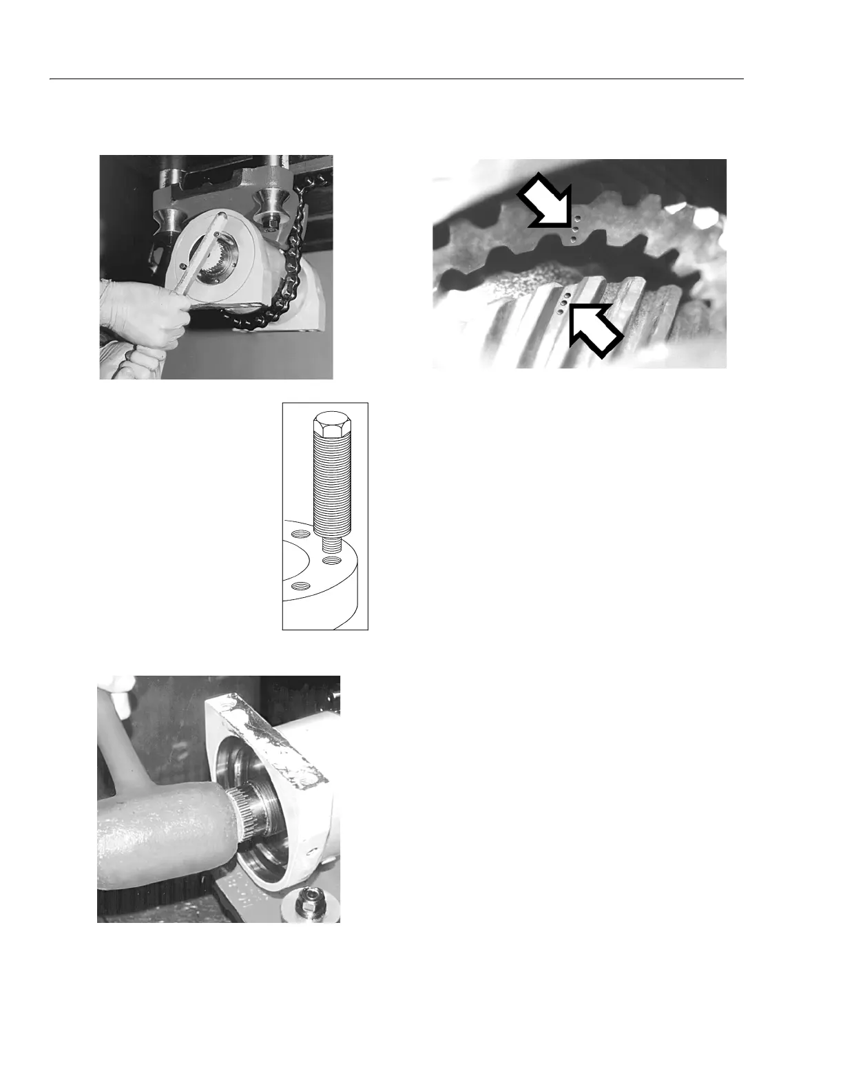
5. Remove the shaft from the housing assembly by
driving it out with a plastic hammer as seen below.
Before the shaft and piston gearing are completely
disengaged, note the orientation between the spline
teeth: small punch marks on the face
of the piston
and the root of a spline tooth on the shaft gearing
indicate timing as seen below
.
Marking the teeth at this time with a permanent felt
tip marker will make the
marks easier to see and
greatly simplify actuator timing during reassembly.
For 120° rotation actuators, remove the stop tube
from the shaft before removing the shaft from the
housing. Do not remove the 0-ring from the stop-
tube. It performs no sealing functions and should be
reused when the actuator is reassembled.
 Loading...