11
up only one component of the constrained forces) in the form of a periodic sine wave.
The signal is not perfectly sinusoidal, due to noises from the suspension system, which add to the signal generated by
the imbalance of the wheel. To determine acutal imbalance the signal must be • ltered.
To • nd wheel imbalance, the transducers signal magnitude and encoder timing are both required.
A series of timing marks on the shaft that interrupt light transmitted between two optocouplers generate a DC Square
wave each time a mark moves past an optocoupler. One additional mark offset from the encoders’ metallic strip, inter-
rupts a third optocoupler on the board, creating a zero-signal reset or home position.
The encoder detects 512 angular positions during each turn of the shaft, plus the home or reset position.
The frequency of the DC square wave generated by the encoder allows the balancer to compute shaft speed, wheel
acceleration and weight location. The encoder and transducer signals are multiplexed by the Processor section of the
Integrated Display, to give weight amount and location readings.
The Processor section gathers the information generated from the encoder and transducer via a ribbon cable. This
board is powered with 5VDC received from the Power Supply section of the Integrated Display.
Calculated imbalance values are then shown on the display after a spin cycle.
2.6 INSTALLATION PRECAUTIONS (Floor Level)
All models of Wheel Balancers have to be placed on a well levelled ! oor (± 1º tolerance). If you have already veri• ed
the ! oor levelling, skip this section, otherwise proceed as explained below.
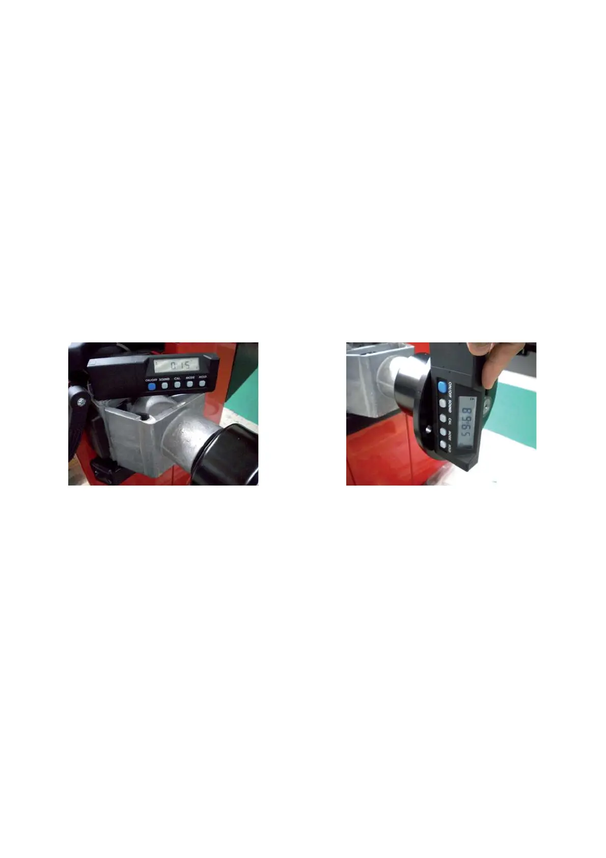
Remove the weights tray and check the levelling by mean of a spirit level or electronic inclinometer.
1. Put the level on the vibratory system (Fig.1). The value must be 0° ±1º.
2. Put the level vertically on the ! ange (Fig.2). The value must be in the range 90º± 1 °.
Fig.1 Fig.2