6
CHAPTER 1
INTRODUCTION
1.1 GENERAL
This Service Manual describes maintenance, checks and repairs operations of the wheel balancer and is for use of
quali! ed personnel only.
Keep this manual constantly updated, by adding Service Bulletins related to the balancers.
IMPORTANT!
The identi! cation datas of each machine are printed on an adhesive label attached to the rear or the left side of the
machines. The serial number is a sequence of ! gures standing for the manufacturing month and year the ! rst four
numbers, followed by the machine part number made of 7 numbers or alphanumeric and ! nally the progressive serial
number of the machine manufactured with this speci! c part number.
1.2 TOOLS REQUIRED
To repair and/or check these balancers, the following standard tools are required:
Wrenches : 6 mm to 19 mm
Allen keys : 2.5 mm to 8 mm
: 6 mm, with a length (or adapter) of at least 140 mm (ratchet advised)
Screw drivers
: Flat bed, 1 to 3
: Phillips, 1 to 3
: Magnetized Phillips 300mm long.
Multimeter : AC, DC, A, Ohm, pF
User Calibration Weight (supplied with the unit)
Special tools that are required for speci! c tasks are:
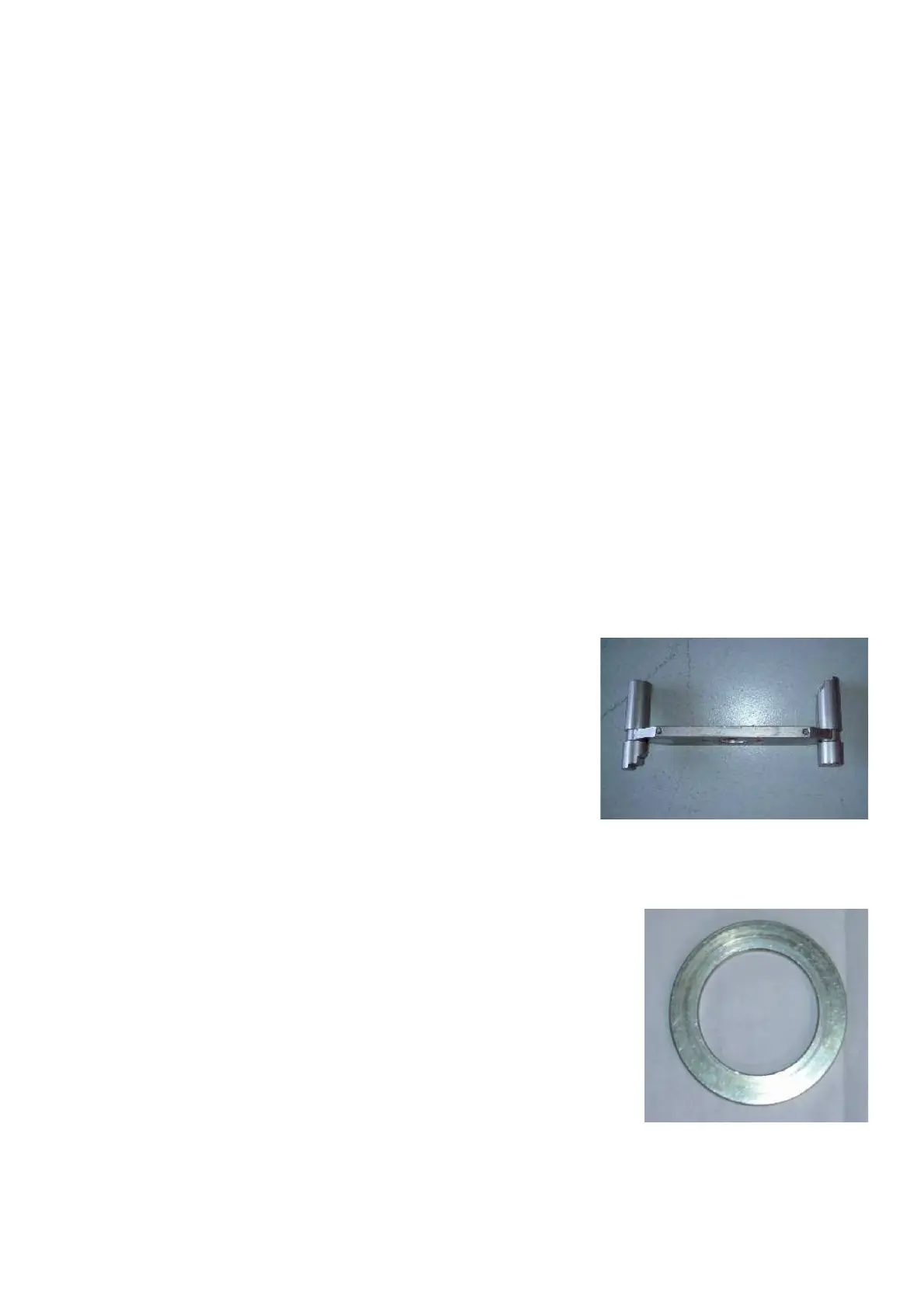
Test Rotor : # EAA0277D12A
Use this test rotor to perform a Factory Calibration, Service
Code C115, C88. This is required after:
Ø The replacement of a complete Vibratory System.
Ø Replacement of the transducers.
Ø Replacement of the Integrated Display.
Ø A complete loss of the con! guration data.
Ø Control of the balancers calibration.
Calibration ring: # 0025424 (included with test rotor # EAA0277D12A)
Use this ring on P variant machine only to perform the compensation of imbalance
main shaft.
Service Code C84. This is required after:
Ø The replacement of a complete Vibratory system.
Ø A complete loss of the con! guration data.
Ø The replacement or reparation of the power clamp device.
Ø After power clamp " ange replacement.
Ø Replacement of the transducers.