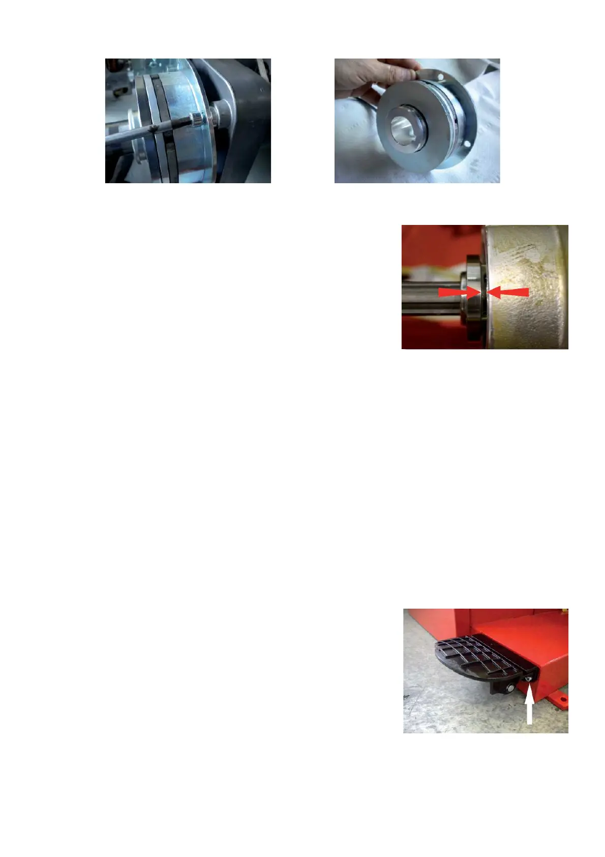
Ø Using a 2.5mm hex key securely tighten each set screw. This will push
the pulley sheave to the right while the collar tightens securely against the
C-Clip and will create a gap between the collar and the pulley sheave.
Ø Mount the belt and the drive pulley optoencoder.
Ø Mount the power clamp device.
Ø Connect the electromagnetic brake wires to the connector X3 of the IBP box.
Ø Mount the weight tray.
Ø Switch on the machine.
Ø Calibrate with C84.
Ø Check if the balancer works ! ne.
4.22 CHECK AND REPLACEMENT OF ELECTRIC BRAKE / CLAMPING PEDAL SWITCH
" : Medium and big Phillips screwdriver, 3, 5 and 6mm allen key, 10mm wrench, scissors.
6 : 2.5h
i : Defective mechanical brake cable may cause the following malfunctions:
1. Machine does not clamp or unclamp.
2. Balancer show E89 turning it on.
3. 001090 during wheel clamping
4. 001091 during wheel unclamping
TO CHECK THE SWITCH
Ø Turn on the balancer and check the switches with service code C56.
Ø Remove the two screws securing the brake pedal assembly.
Ø Remove the weight tray.
Ø Remove the cover from the electronic box.
Ø Rotate either the microswitch activator or the micro switch on the brake pedal assembly until the circuit is open.
Ø Make sure that the circuit closes when the brake pedal is depressed or pressed