28
If it lights up, the +5 V supply voltage is OK.
If not:
- check mains plug, mains switch, mains fuse
- check connector X1 (wiring and placement).
- check the electrical connection between connector X1 and the PEM
If the mains on connector X1 is 150 - 264 V~, then a short circuit or overload condition on the +5 V output may be
present. To locate the possible cause of the condition:
Ø Check the signals to and from the component that is also involved in this trouble shooting search (if relevant)
Ø Check the component that is also involved in this trouble shooting search (if relevant)
Ø Check the signal ! ow from connector to connector. Some signals run straight from connector to connector.
TO CHECK THE CONTROLLER SECTION:
Ø Check for system messages and perform the steps. After that:
Ø Check all connectors and cables for damage
Ø Check the power input:Try to download the correct program by means of a SD card or through the serial interface.
Ø Check the signals to and from the component that is also involved in this trouble shooting search.
Ø Check the component that is also involved in this trouble shooting search.
Ø Check the signal ! ow from connector to connector. Some signals run straight from connector to connector.
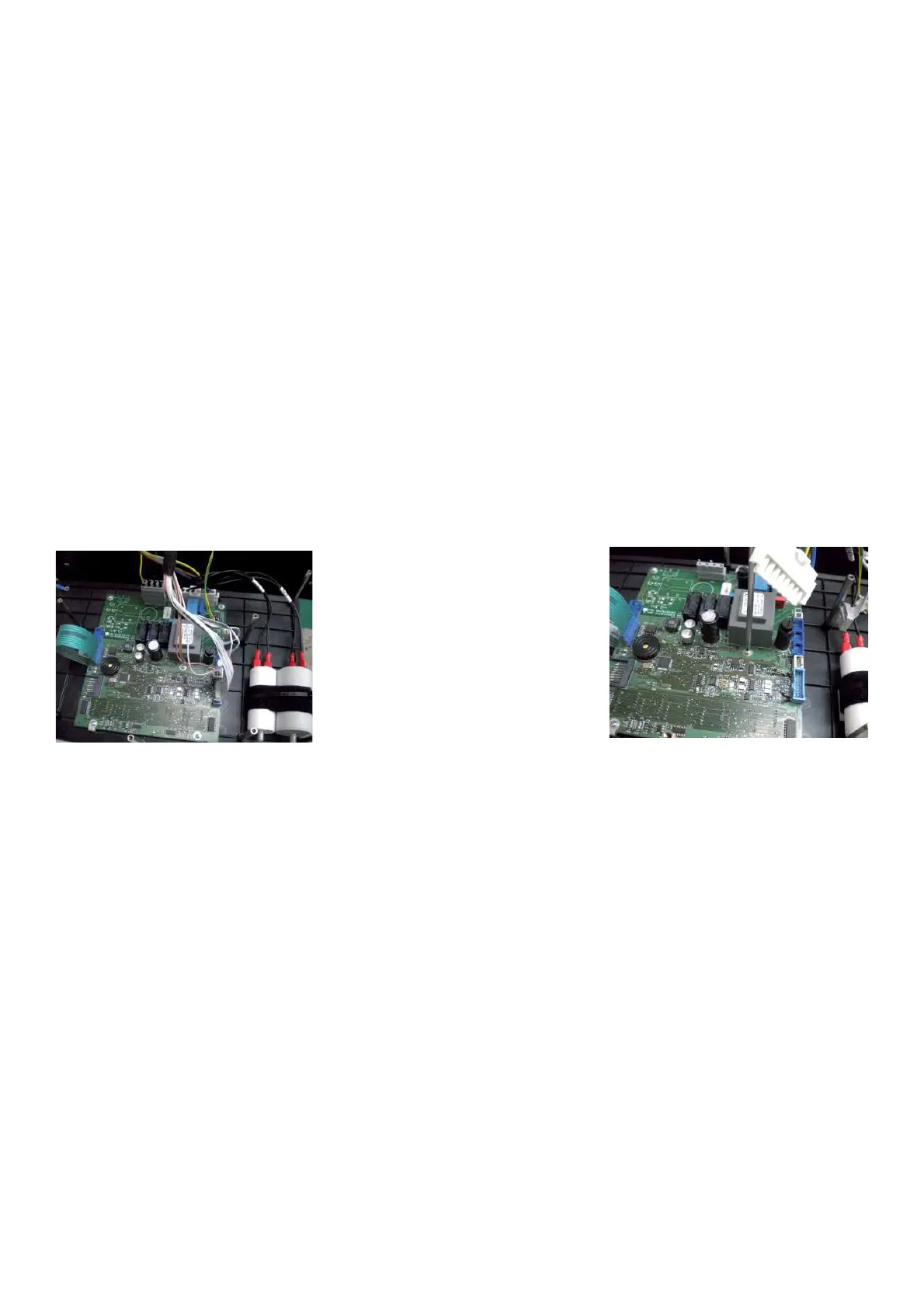
TO REPLACE THE IBP INTEGRATED BOARD
Ø Disconnect power supply from the machine.
Ø Accede to the Integrated IBP board.
Ø Disconnect all connectors.
Ø Remove the Integrated Display Board.
Ø Mount the new Integrated Display board.
Ø Reapply all wiring.
Ø Ensure the green/yellow earth cable is applied on the central earth bracket.
Ø Close and insert the Integrated Display Board into its panel.
Ø Reapply mains cable.
Ø Turn on The balancer.
Ø Perform the C code C86
Ø Check if the machine works " ne.
4.11 CHECK OF VIBRATORY SYSTEM
" : Calibration rotor, electronic or spirit inclinometer
6 : 1h
i : Both bearings are bonded into place in the main shaft. In between the two positions the polygon ring is
positioned.
It is not possible to replace the bearings or the polygon ring: the only solution is replacing the complete main
shaft. To check the vibratory it is necessary to perform the service codes C59,C63, C64, C66, C69, C71, C72,
C74, C75, C103, C104 by using the test rotor.