17
integrated circuit.
The light of the LED is refl ected back to the encoder by one of the 256 mirrors of
the polygon ring, focused by the lens on the four detectors. During rotation of the
main shaft, the mirrors or bars will tilt and defl ect the light across the detectors A,
A`, B and B`. With further rotation in the same direction, the light will hit the next
mirror or bar, and with a full revolution, it will be defl ected 256 times across the
detectors in the above given sequence.
The light detectors A and A` respectively B and B` are connected to one amplifi er.
The difference in brightness between the detector pairs determines the current
state of the output channels A and B. To keep the signals A and B free from
interference, an integrated circuit amplifi es the signals.
An intended irregularity in the arrangement of the mirrors is detected with the
main shaft rotating at constant speed, serving as absolute reference. On detection of the reference, the position
counter is set to zero thus providing absolute angular position of the main shaft.
Checking the incremental encoder is via service code C74.
The surface of the ring has to be clean and shiny. If the ring is not clean, the machine will not work correctly.
IMPORTANT: Before replacing the vibratory system due to suspected encoder ring malfunction try cleaning the
encoder band. Please note: Do not use any cleaning agent (no alcohol, etc.) to clean the plastic polygonal ring!
The red LED of the refl ective encoder IC does not light up immediately after power on, since voltage is applied under
program control!
In the very unluckely event that you will discover a defective polygon ring, the complete vibratory assembly has to be
exchanged. The main shaft cannot be removed from the vibratory tube, as the ball bearings are glued-in.
Non-volatile memory at Optoencoder unit Beside the EEPROM on the Controller board, there is a second non-volatile
memory soldered to the Optoencoder unit. Both EEPROMs should hold the same data: machine model, adjustment
data, counts of counters, selected modes of operation and stored error-codes.
Having two non-volatile memories becomes benefi cial when the Controller board or the electronic box has to be
replaced.
With service code C86, the contents of the EEPROM on the Optoencoder unit can be copied to the EEPROM located
on the Controller board, without having to set the machine model via C47 or having to perform a calibration.
On power up self-test, the contents of the EEPROMs are compared. If differing but valid data is detected, C85 “Copy
contents of the EEPROM on the Controller board to the Optoencoder unit” is displayed.
Do not un-plug connector X6 with power connected. A difference in memory contents of the non-volatile memories
may occur!
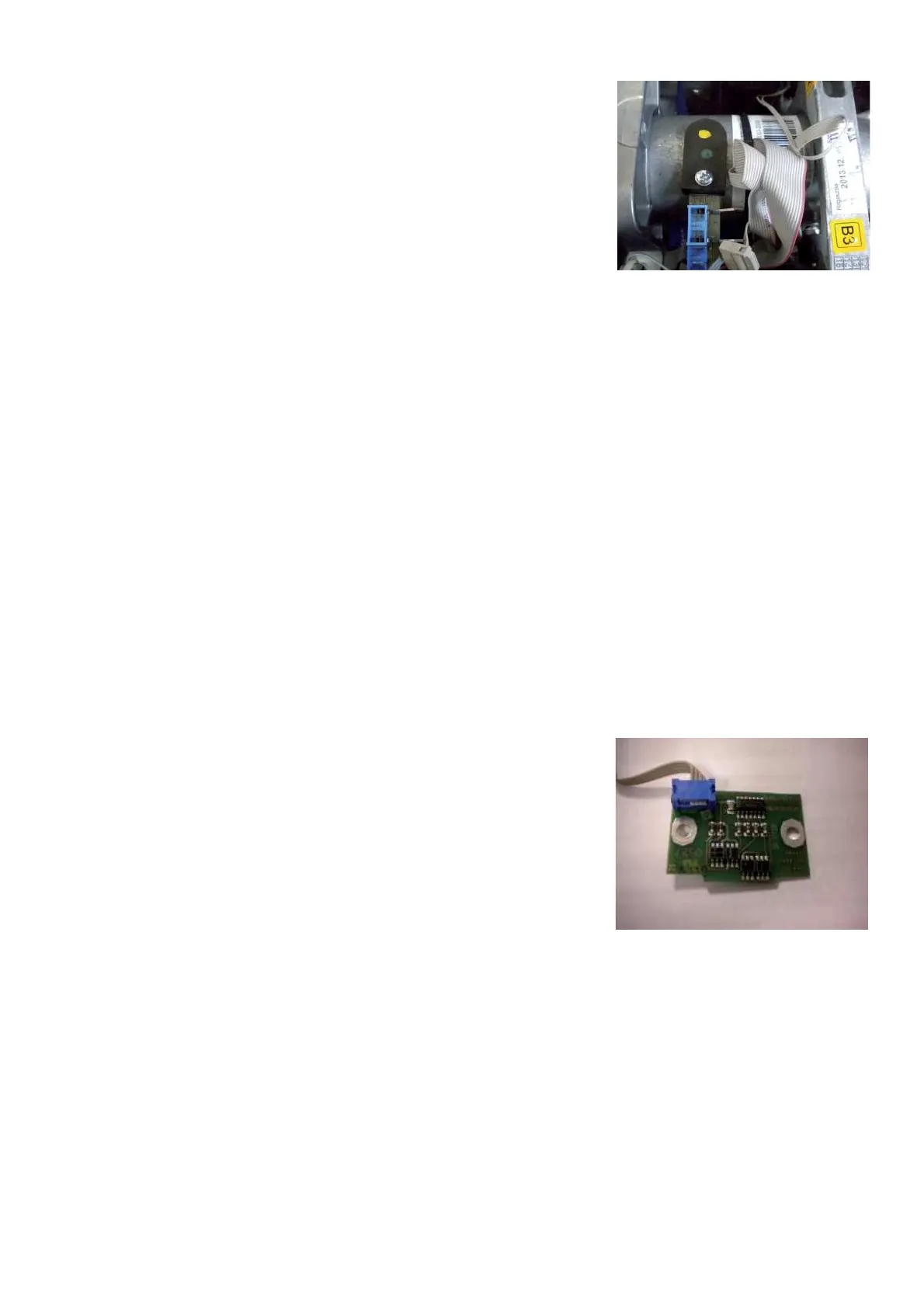
3.12 ENCODER BOARD OF THE POWER CLAMP
Incremental encoder B9 acquires the rotational travel, direction of rotation and
the absolute angular position of the big pulley at the vibratory assembly with
power-clamp. The travel of the tie-rod is derived by program from rotational
travel of the pulley.
The pattern of a code strip, fi xed to the circumference of the big pulley, is sensed
optically by an encoder board positioned 1-mm above the pulley.
The adhesive code strip consists of a transparent foil with alternating black and
white zones (32 increments) printed on.
CAUTION! The wider zone of the zero reference has to be positioned to the
edge of the pulley.
The small encoder board carries four SMT refl ective interrupters, some resistors,
an integrated circuit (Hex-Schmitt-Trigger) and a 4-position ribbon cable with receptacle.
The refl ective interrupters A and A` respectively B and B` are placed with a radial offset of half an increment, so the
interrupters work in a push pull arrangement. The push pull mode of operation makes the encoder sensitive to the light
output of the infrared LEDs and the refl ectance of the code strip. The lateral offset of the interrupters A to A` respectively B
to B`is essential for the push pull operation for the zero reference as well. In this way the zero reference marking with its 25
to 75% mark to space ratio can be mapped complementary on the two tracks.
The analogue waveforms at the phototransistors of the interrupters are converted to sharp edge square-waves with low
output impedance by the Schmitt-Trigger circuit.
The encoder board is fastened via a plate screwed to a corner bracket to the stator of the electromagnetic brake. The
corner bracket and the plate serve also to keep the abrasion of the brake lining away from the encoder. To compensate
for lateral work tolerance, the encoder board can be aligned to the code strip with the aid of the movable plate. The two
standing back edges of the encoder board should be in line with the left-hand edge of the code strip.
Incremental encoder B9 can be checked with code C98.
CAUTION! Too much abrasion from the brake lining on the encoder board or code strip will degrade the function of the
incremental encoder. Both parts should be cleaned with a soft cloth or brush occasionally.