22
CHAPTER 4
SERVICE
4.1 INTRODUCTION
This chapter will describe how to check and replace the components of the balancers described in Chapter 2 in the
same order.
NOTE: BEFORE OPENING THE MACHINE FOR SERVICE, DISCONNECT ELECTRICAL SUPPLY LINE AND USE
THE LOCKOUT / TAGOUT PROCEDURE.
4.2 POWER SUPPLY CABLE: CHECK AND REPLACEMENT
" : Voltmeter.
6 : 30’
i : Turning the balancer on it shows 001036
Turning the balancer on it shows 001037
Turning the machine on, the balancer makes the self test but the display does not show anything.
Turning the balancer on it showsC10800
Ø Go to C55 to check the power supply.
Ø Disconnect the power supply from the balancer or from the display.
Ø Using a VOM check for an output voltage at the end of the power plug, +/- 10%VAC VPI, compared to the
nominal.
Ø If there is not the correct output voltage the cable must be replaced.
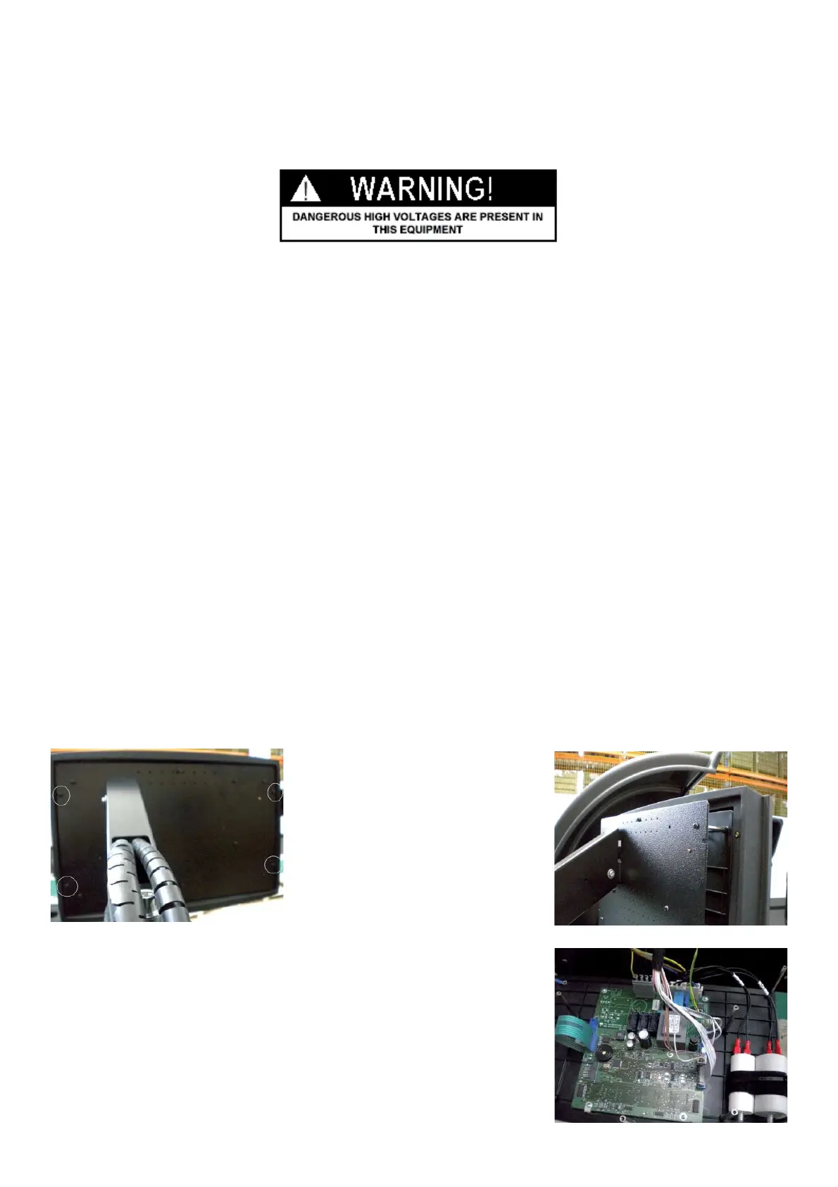
4.3 TO ACCESS TO THE NTEGRATED DISPLAY AND TO THE INSIDE OF THE MACHINE
" : Big and Medium Phillips screwdriver, scissors,
6 : 30’
i :
Ø Disconnect the power supply from the balancer.
Ø Remove the four lateral screws from the back, that hole the plastic frame to the display panel.
Ø Gently slid off the plastic frame.
Ø Remove all other screws from the back of the panel to access to the the
integrated Integrated display board.