15
3.7 V.P.M. VIBRATORY ASSEMBLY
This balancer is equipped with a V.P.M., Virtual Plane Measurement, Vibratory Assembly technology. Instead of using
force measurement at widely apart positions, a compact set up is constructed . It is composed as following:
- The main shaft
- Two transducers
- The optoencoder unit
- The power clamp optoencoder (power clamp version only)
- The motor
The vibratory assembly is the central module of all wheel balancers.
It consists of the force guidance structure for directing the alternating unbalance forces via the transducers. The main
shaft is supported on ball bearings in the vibratory tube with the wheel adaptor at the right-hand end. The drive system
is then propelling and stopping the main shaft.
The incremental encoder B8 is acquiring rotational travels, direction of rotation and absolute angular position of the
main shaft.
The vibratory assembly is fastened and supported towards the ground by the cabinet, so that unbalance produces a
minimum of vibration while the wheel is rotating.
To measure the unbalance, the wheel is clamped to the main shaft; the shaft is accelerated to measurement speed,
with the electronic unit acquiring the signals of the incremental encoder and the unbalance transducers.
The vibratory assemblies utilise the Virtual Plane Measurement force guidance structure. With this force guidance
structure, inadvertently produced forces and the unbalance forces are directed horizontally via the transducers in
an almost a one to one ratio, thus avoiding overload. Without the lever action of conventional vibratory assemblies,
interfering vibrations and changes in transducer sensitivity caused by temperature changes, fatigue, overload,
humidity, etc. have minimum effect thus achieving good long-term and repeatable measurement accuracy.
The unbalance transducers are located in close proximity inside the cabinet. Exposed to almost identical temperature,
temperature variations have little effect on plane separation. The cabinet supports transducer B2, located in the rear.
Transducer B3 at the front is clamped 7° diagonal between the vibratory tube and vibratory plate. Two leaf springs
provide mechanical pre-stress to the transducers.
ATTENTION! Other machine parts must not obstruct the barely discernible movements of the vibratory assembly.
Does the bowden cable touch the cabinet immediately below the vibratory assembly, or the weight tray rests on the
vibratory assembly, part of the alternating forces produced by unbalance are conveyed to the cabinet, side-stepping
the transducers. That kind of force bypass can have considerable negative effect on measurement accuracy.
The advantages of this Virtual Plane Measurement construction are:
- Only horizontal forces are measured by the transducers
- Hardly any external based interference, as the transducers are close to each other and temperature
compensated
- The (virtual) measurement planes are positioned outside the balancer cabinet, at least 1.5 meters / 4.9ft to
the left and at the shaft’s ! ange.
3.8 TRANSDUCERS
Two transducers and the accompanying temperature sensor are used with all
variants of the vibratory assemblies and they are installed in a manner that they
form a virtual transducer on each end of the shaft. Both measuring transducers
are arranged in one plane.
The rear transducer pick up alternating forces of the left-hand virtual measuring
plane and is supported on the machine housing. The front measuring transducer
is clamped between the vibratory tube and vibratory plate and converts the
alternating forces of the right-hand virtual plane into a proportional electrical
charge. Charge ampli" ers on the processor board convert the transducer outputs
to alternating voltages.
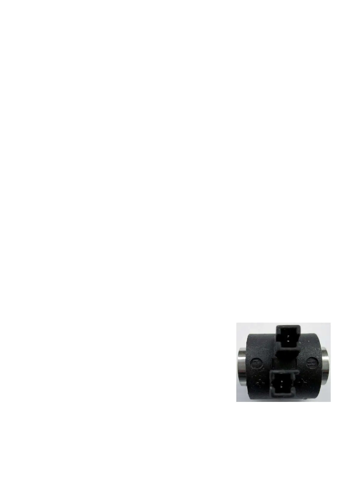
A transducer consists of a single piezo disc with contact plates; insulation discs
and thrust spreading members at both sides of it. This sandwiched arrangement
is encapsulated by a moulded case of black plastic. The slotted terminal strips of the two contact plates jut out of the
plastic case, protected by collars. Connection to plug X4 is via the wire harness, by means of insulation displacement.
The wires from position 12 and 16 of connector X4 are marked with a small black band and have to be connected to
the transducer terminals marked with the embossed +. Wires 11 and 12 of X4 hook up transducer B3 located at the
front, wires 15 and 16, connect transducer B2 at the rear of the vibratory assembly.
To make the insulation displacement connection to the transducer, proceed as follows:
a) To connect a transducer to an already used wire harness, cut off the wire ends at the notches.
b) Check the position of the terminal strips relative to the surrounding collar.
If the pointed ends of the terminal strip are 0.6mm / 0.024inch below the edge of the collar, contact problems can
arise.