29
4.12 REPLACEMENT OF THE ALLOY VIBRATORY SYSTEM
" : 2.5, 5 and 6mm allen key, 17mm wrench , Medium and big phillips screwdriver, scissors.
6 : 2h
i : Defective vibratory assembly may cause the following malfunctions:
1. After the balancing cycle the machine show error 001021.
3. The balancer shows wrong balancing values.
4. The balancer chases weight.
5. The shaft shows excessive play.
Ø Remove the ! ange or the balancing shaft from the balancer.
Ø Turn the machine off.
Ø Disconnect the power supply from the the machine.
Ø Remove the display panel.
Ø Remove the weight tray and plastic plugs rom the front of the cabinet.
Ø Disconnect the ! at cable of the Optoencoder, transducers from connector X4 of the Integrated Dispaly.
Ø Remove the laser pointer from Vibratory assembly.
Ø Disconnect the motor cable.
Ø Disconnect the brake pads.
Ø Remove the rear transducer .
Ø Remove the three plastic plugs from the cabinet to access to the hex vibratory assembly bolts.
Ø Using 1/4”/6mm hex head remove the six hex bolts to the vibratory. Pay special attention of spacer placement.
Ø Lift up on the vibratory member and remove. Be careful not to damage wiring, boards, etc.
Ø Set vibratory member into the balancer housing. Be careful not to damage wiring, boards, etc.
Ø Insert spacers.
Ø With the aid of a helper start the two lower hex bolts.
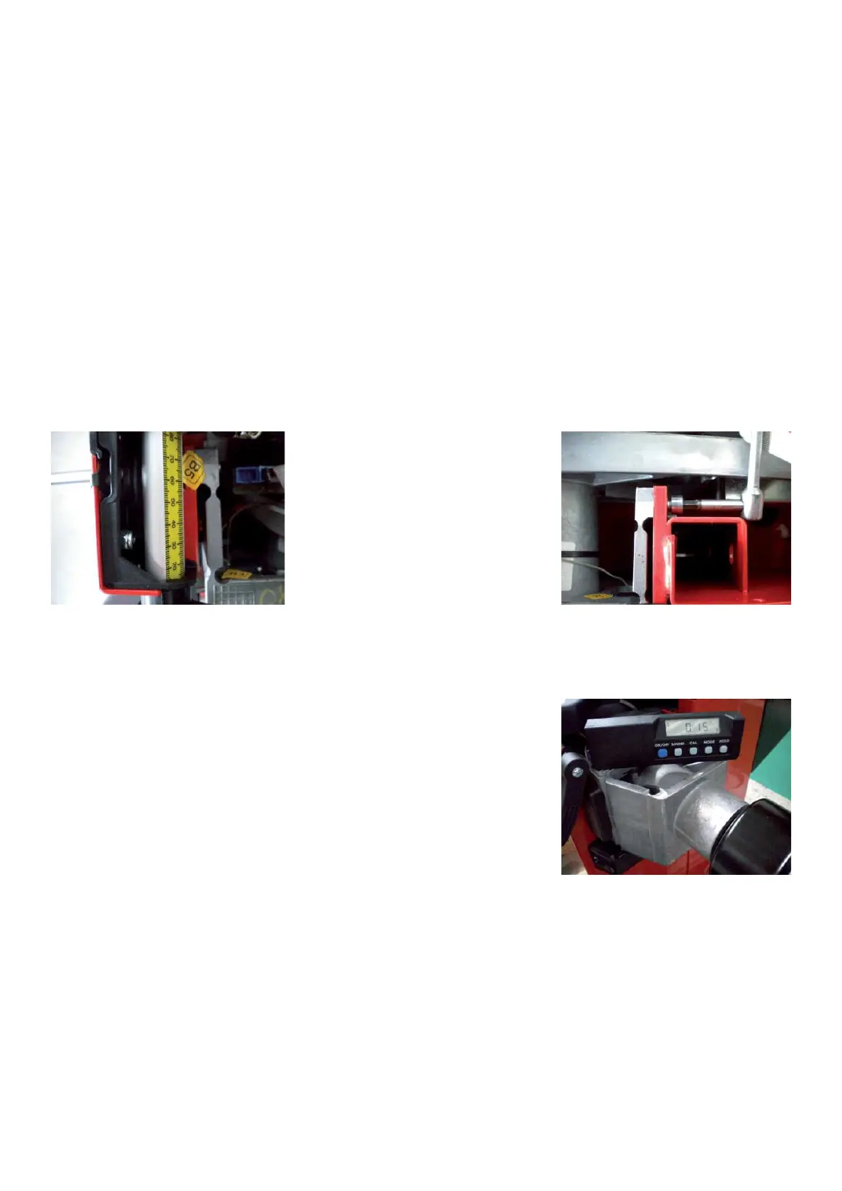
Ø Install the 4 remaining hex bolts tighten to 25Nm / 18.4lbfts and make sure
that the vibratory assy is properly levelled.
Ø Install the rear transducer following 4.13
Ø Install all the cables.
Ø Install the laser pointer to Vibratory assembly.
Ø Install weight tray and the plastic plugs.
Ø Connect power supply and follow all calibration procedures C85 .
Ø Perform the calibration C115, C84, C88, C81, C122, C82.
Ø Check isf the balancer works " ne.
4.13 CHECK AND REPLACEMENT OF TRANSDUCERS ON ALLOY VPM
" : 2.5, 5 and 6mm allen key, 17mm wrench , Medium and big phillips screwdriver, Scissors, Calibration rotor, Fork
tools, dynamometric key,
6 : 1h each one
i : Defective transducers may cause the following malfunctions:
1. The balancer shows error C10410.
2. The balancer shows error C10420.
3. The balancer shows error C10430.
5. The balancer shows wrong balancing values.
6. The balancer chases weight.