18
3.13 MOTOR DRIVE SYSTEM
Description: The primary functions of the motorised drive
system are to accelerate the main shaft, with the wheel
clamped on it, up to the measurement speed, keeping the
speed constant during measurement and subsequently
slowing down to a dead stop. Acceleration and deceleration
should be rapid but with controlled torque, avoiding slippage
of the wheel on the adaptor.
During unbalance measurement, no vibrations should be
generated by the drive system.
With some variants of the vibratory assembly, the drive
motor is used for breaking as well.
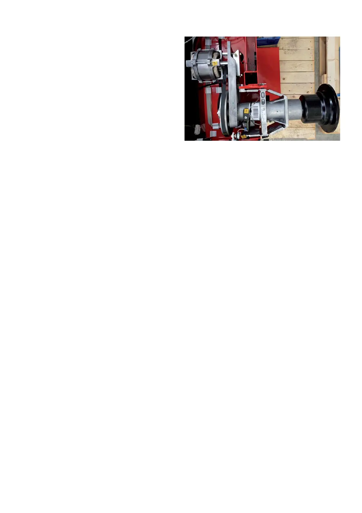
The drive system consists of the motor fastened to a
bracket, secured to the vibratory tubing. The small pulley at
the motor, the big pulley at the left end of main shaft and the
multi-V belt as well. The screws fastening the motor to bracket are also used for belt tension adjustment.
The big pulley is seated on the tapered left end of the main shaft and fastened wit one central screw M8. For
separating the big pulley, the central bore is furnished with a thread M12.
On power clamp version the big pulley is secured on the tapered shaft by preloaded collar and C clip.
After putting the big pulley back on the shaft, main shaft unbalance has to be compensated using code C84.
With a single-phase squirrel cage motor with a nominal voltage of 230-volts AC and a maximum current of 4,5 A, the
power requirements of the balancers can be easily met. It can be hooked up to 50 or 60 Hz line frequency via a plug
to ordinary wall outlets.
The drive system will work in a range of 170 to 264 volts AC. With 115 line voltage, a stepup transformer should be
! tted inside the cabinet.
Function: Irrespective of line frequency, the drive system accelerates to the preset speed within a range of 80 to 200
RPM. With the speed still near zero after half a second, full motor torque will be applied. This is for preventing speed
overshot with low " ywheel mass as there might be no wheel guard ! tted with a low speed balancer.
At reaching the pre-set speed, torque is cut back. The low torque is set to a rate, compensating the friction, for the
most part, caused by the belt and by air drag of the wheel.
Torque reduction is accomplished by lowering the voltage supplied to the motor with an AC controller, located on the
Integrated Display board. Using semiconductor devices, this novel AC controller provides arc-less switching for a long
service life.
Unbalance measurement is carried out with reduced torque at slightly in- or decreasing speed of the main shaft,
hence avoiding pendulum oscillations in the motor.
Measurement speed can be held within set bounds to any length of time by varying the motor torque. Detecting the
speed via the incremental encoder B8, speed control is implemented in software by varying the pulse-duty factor
to the AC controller. Subsequently, the already reduced voltage supplied to the motor is varied by 5% (dual-mode
control).
With more than 150 RPM of main shaft speed, the torque capacitor CT is switched off by relay under program control.
With increasing speed, the effect of CT on torque drops and reactive current increases.
Direction of rotation of the main shaft is appointed by the order of wires attached to its connector.
3.14 BELT TENSION
With the drive system, belt tension is crucial as it has great in" uence on friction.
Friction can hinder extended measurement runs, e.g. service code C63. If friction uses up more energy than supplied
to the motor during prolonged measurement, the speed will drop and measurement will be stopped. During a normal
balancing cycle (10 revolutions) with a wheel clamped on, the effect of friction will hardly be noticed. Before the speed
reduction becomes signi! cant, unbalance data collection is completed and the brake is turned on. Excessive belt
tension puts extra load on the ball bearings and can reduce measurement accuracy.
With the belt too slack, it will slip causing premature wear and in most cases, disturbing squeaking noises as well.
3.15 THE BRAKES
These balancers are equipped by brakes of two different design depending the wheel clamping. All brakes
have controlled torque, to avoid slippage of the wheel on the adaptor, preserving counterweight positions.
Ø Brakes for decelerating the main shaft after completion of unbalance measurement.
Ø On power clamp version, position brakes under program control for stopping of the slowly rotating main shaft,
with one of the compensation locations at the top (12-o’clock) or other wanted position:
a) Braking at the compensation location of the left-hand plane after measurement.