30
TO CHECK THE TRANSDUCERS:
Ø Check with C64, C66, C71, C103, C104.
Ø Select the C75 AdE 1 and AdE 2 are read out on a board and the voltage difference between the outputs of the
unbalance signal ampli! ers N4A and N4B is indicated. AdE 2 is the channel indicating the signal of transducer B3
located in the front. AdE 1 is the channel indicating the signal of transducer B2 located in the back. Normally, the
readings are " uctuating around ±0.005x volts.
Ø Standing in front of the balancer, push at the end of the main shaft repeatedly by hand and
observe the readings.
(Pushing at the " ange will put inadequate force on the front transducer, since this plane is the pivot axis of the
force guidance structure.)
If there is no effect on the readings, the transducer is not connected properly.
If the two wires are connected in the order intended, there is a minus sign as long you press. Pushing by hand,
readings of 0.5xxx volts are easily obtained.
Ø In order to assess the relevant insulation resistance; do not touch the machine, just read theindicated voltage.
With the transducer in the humidity for several days, the insulation resistance can decline to less than 500 Meg
Ohms. Insulation resistance of 500 Meg Ohms will produce 0.14 volts at the input of the analogue to digital
converter.
Ø Press the minus key to select channel #AdE 1#, transducer B2 in there is connected to, and repeat the above
steps to check the rear transducer.
TO REPLACE THE TRANSDUCERS:
Ø Disconnect the power from the rear of the machine.
Ø Remove the weight tray.
Ø Remove the protection underneath the Vibratory assembly.
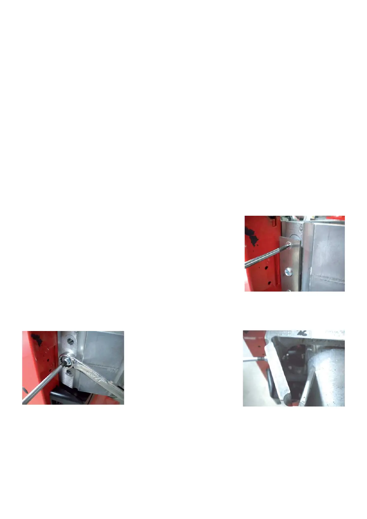
Ø Using a 2.5mm hex key remove the preloading plate.
Ø Using a 17mm wrench loosen the jam nut.
Ø Using a 5mm hex key, back the set screw off by turning counter/clockwise. Do not lose the ball bearings on each
end of the tranducers. These allow the transducer to center easily on the vibratory member.
Ø If the transducer is being replaced , the lead “+” is already signed on the wire with a black band. Cut the two wires
at the transducer.
Ø The transducer attached to wires 11 and 12 of connector X6 is placed in the front; that one attached to wires 15
and 16 is placed in the rear of the vibratory assembly.
To ! t and mechanically pre-load a transducer, carry out the following steps:
Ø Insert the wires into the transducers: the cables with black band must be ! tted on the positive lead.
Ø The two setscrews M10x1x29 with ball sockets (inverse cones) should be screwed into the vibratory plate of 20-
mm / /0.79inch thickness and the rigid support plate welded to the cabinet.
Ø Put some stiff grease in the recesses at both ends of the transducer.
Put 8-mm Ø ball bearing in the recesses.
Ø Insert the transducer in the slot of the vibratory plate with one of the balls contacting the indentation opposite the