31
setscrew. Tighten the setscrew until the transducer is centered.
Ø Route the transducers with leads downward to avoid any possible condensation concentration inside of the leads
them selves.
Ø Screw on the locknut M10x1 (17-mm across the ! ats), but do not tie up yet.
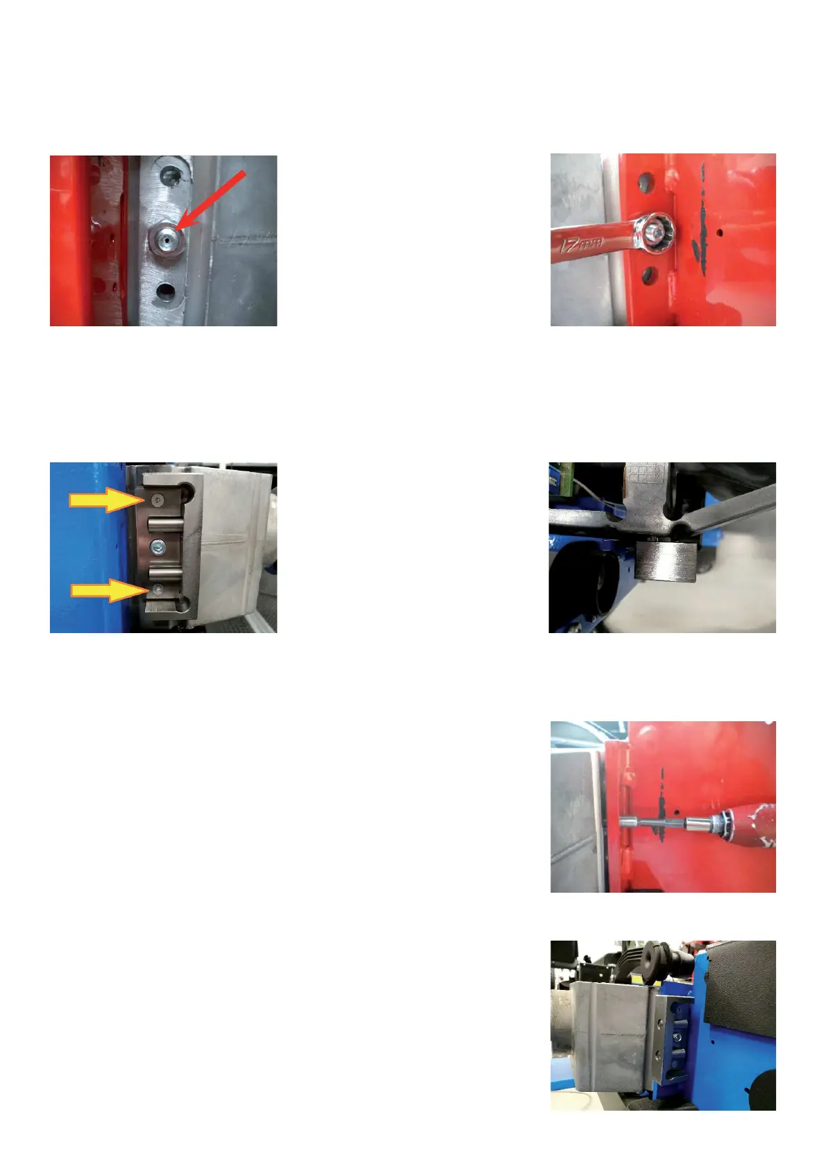
Ø Tighten the M10x1setscrews at 0,40 ± 0,05 Nm (3,5 ± 0,4 lbs-in) shown by red arrow.
Ø Fasten the locknut. To prevent the setscrew to turn, hold it with the hexagon wrench 5-mm inserted.
TO ADJUST THE FRONT TRANSDUCER
Ø Place the spacer # EAA0470G84A, on the spring plate as shown in the pictures below.
Ø Tighten the screws (orange arrows) at at 0.50 ± 0,05 Nm (4,4 ± 0,4 lbs-in), then remove the spacer, making the
backward movements.
Remark: The tightening torque is necessary to ensure the correct preload to the spring plate.
TO ADJUST THE REAR TRANSDUCER
Ø Tighten the the M10x1setscrew at 0.50 ± 0,05 Nm (4,4 ± 0,4 lbs-in).
Ø Fasten the locknut. To prevent the setscrew to turn, hold it with the hexagon
wrench 5-mm inserted.
Ø Drive in the screws M4, so that the leaf spring is in equal distance at both ends but not bend in the middle.
Ø Place the spacer # EAA0470G84A, on the spring plate as shown in the
picture.
Ø Tighten the screws (red arrows) at 1,00 ± 0,05 Nm (8,4 ± 0,4 lbs-in), then
remove the spacer.