43
TO ADJUST AND REPLACE THE SWITCH
Ø Lift the balancer from the ! oor.
Ø Remove the defective switch from the pedal.
Ø Remove the weight tray.
Ø Release the switches wires inside of the cabinet.
Ø Cut the wires of the defective switch and connect them to those ones of the new switch.
Ø Remove the wires of the defective switch from the connector X13
Ø Fit the new switch on the pedal bracket and secure it with a torque wrench at 0.5Nm / 4,4 lbs-in)
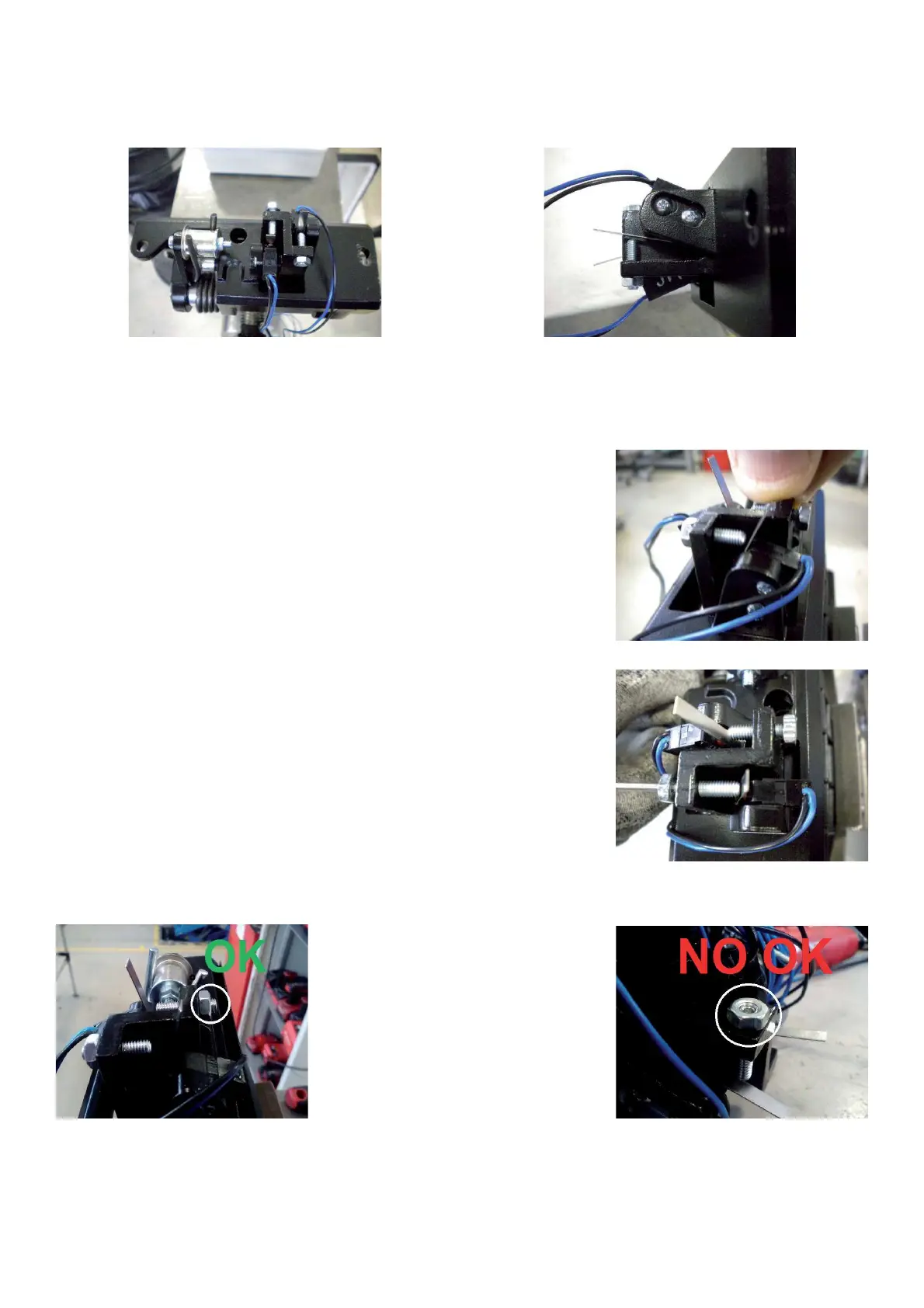
Ø Check the adjustment of the switch by pressing the pedal until end of stroke:
when the pedal is at the end of its
stroke the micro switch must be must be
activated but between the actuator and its body there must be a gap of at
least 1,7 mm.
Ø Tighten or loosen the set-screw M4 in order to obtain the right adjustment
and secure with the nut.
Ø The head of the set-screw should protrude 2-3 mm from the surface of the nut. Otherwise repeat the adjustment
procedure and/or ask for parts inspection.
Ø Pull out the new wires through the cabinet
Ø Install the new switche wires to the connector X13.
Ø Fit the pedal assy to the balancer.
Ø Turn on the machine and check if the brake and the power clamp switches work " ne.If the functions are reversed,
reverse the wires on the connector X13.
Ø Mount the weight tray.