37
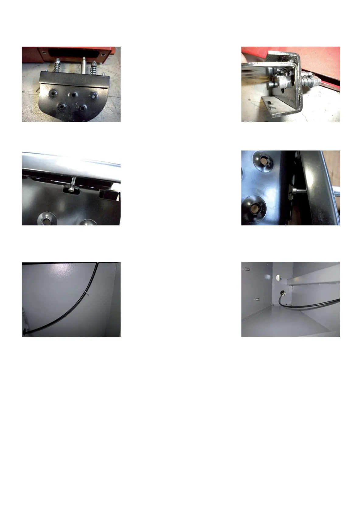
Ø Pull out the pedal assy with the Bowden cable from the cabinet.
Ø Dismount the screws to separate the pedal from the pedal bracket.
Ø Pull out the Bowden cable from the pedal
Ø Install the new Bowden cable on the pedal.
Ø Mount the pedal to the bracket.
Ø Pull in the Bowden cable through the protective ! ex tubing inside of the cabinet.
Ø Tighten the pedal assy to the cabinet.
Ø Install the nuts on the Bowden brake cable without lock them
Ø Mount a standard 15” tire and wheel assembly.
Ø Using your foot apply pressure to the foot pedal assembly.
Ø Using a 10mm wrench hold the nut located at the top of the cable.
Ø Using a ! atblade screwdriver turn the cable counterclockwise to apply tension to the brake or clockwise to loosen
the brake.
Ø The cable is properly adjusted when the tire and wheel assembly has a little resistance.
Ø Lock " rmly with the counter nut.
Ø Mount the weight tray
Ø Mount the display panel