JOHNSON CONTROLS
17
FORM 155.17-N1
ISSUE DATE: 4/1/2013
3
SECTION 3 – UNIT RIGGING
Only qualied rigging personnel should
handle the rigging operation. Failure
to observe this may result in equipment
damage, serious injury or death!
For unit weights and dimensions, see Table 3 on page
87 in Appendix A at the back of this document.
Rigging diagrams for specific ParaFlow™ unit mod els
are located in Appendix B (Figure 44 on page 95 )
The following guidelines must be followed when rig-
ging the unit:
1. When using single point lifting, do not place the
slings at more than a 60° angle. See diagrams in
Appendix B for illustration.(Figure 44 on page
95 )
2. If slings will be at more than a 60° angle, use
spreader bar.
3. Only rig the unit horizontally! Do not slant the
unit while moving it. If the unit is to be installed
in a sub lev el basement or where it can only be
rigged slanted, contact Johnson Controls for spe-
cial instructions prior to rigging. This should be
done prior to ordering, to check feasibility.
4. Lifting eyes are mounted at the top of the “S”-
type se ries units for rigging. Choose a chain ac-
cording to the min i mum length requirement in
column “C” under the “S” Unit Rig ging table.
Place the hooks in the eyes and lift unit to the ap-
pro pri ate lo ca tion.
5. Do not sling on or against any projecting brack-
ets, pumps, valves, pipes, ttings, etc.
6. Do not lift the unit using the holes at the corners
of the end sheets. These holes are manufacturing
lift ing holes and are not designed for lifting the
com bined weight of a completely as sem bled unit.
FOUNDATION
Unit foundations are usually made from concrete with
a compressive strength rating of not less than 4000 psi
and are able to support the full operating weight of
the unit (see Ap pen dix A Table 3 on page 87– Unit
Weights and Di men sions, for the par tic u lar unit mod-
el). When lay ing a con crete foun da tion, use steel to
reinforce the con crete and fin ish the sur face smooth ly.
The con crete foun da tion pad must be lev el with in 1/4
inch at all the mount ing lo ca tions of the unit.
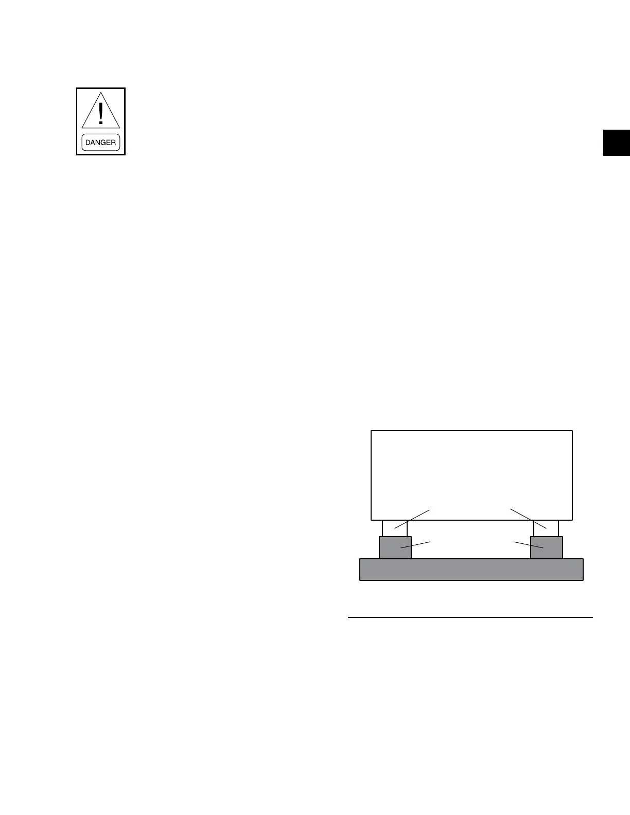
If the ceiling height in the equipment room per mits,
it is advantageous to have a por tion of the foun da tion
el e vat ed just where the chill er legs will set upon the
con crete. This allows for greater clear ance be neath the
chiller for service work such as tak ing so lu tion sam-
ples, pulling pumps, etc. For de tails on where the chill-
er feet will rest (chill er foot print), see the ap pro pri ate
YORK “Di men sions and Phys i cal Data” forms as list-
ed in the Introduction Section of this doc u ment.
See the ap pro pri ate ta ble in Ap pen dix A Table 3 on
page 87 at the back of this doc u ment for unit di men-
sions, and weights.
YORK ParaFlow
Chiller/Heater
TM
CHILLER FEET
ELEVATED SECTIONS
(Risers)
FOUNDATION PAD
FIGURE 3 - FOUNDATION PAD
ld05297
 Loading...


