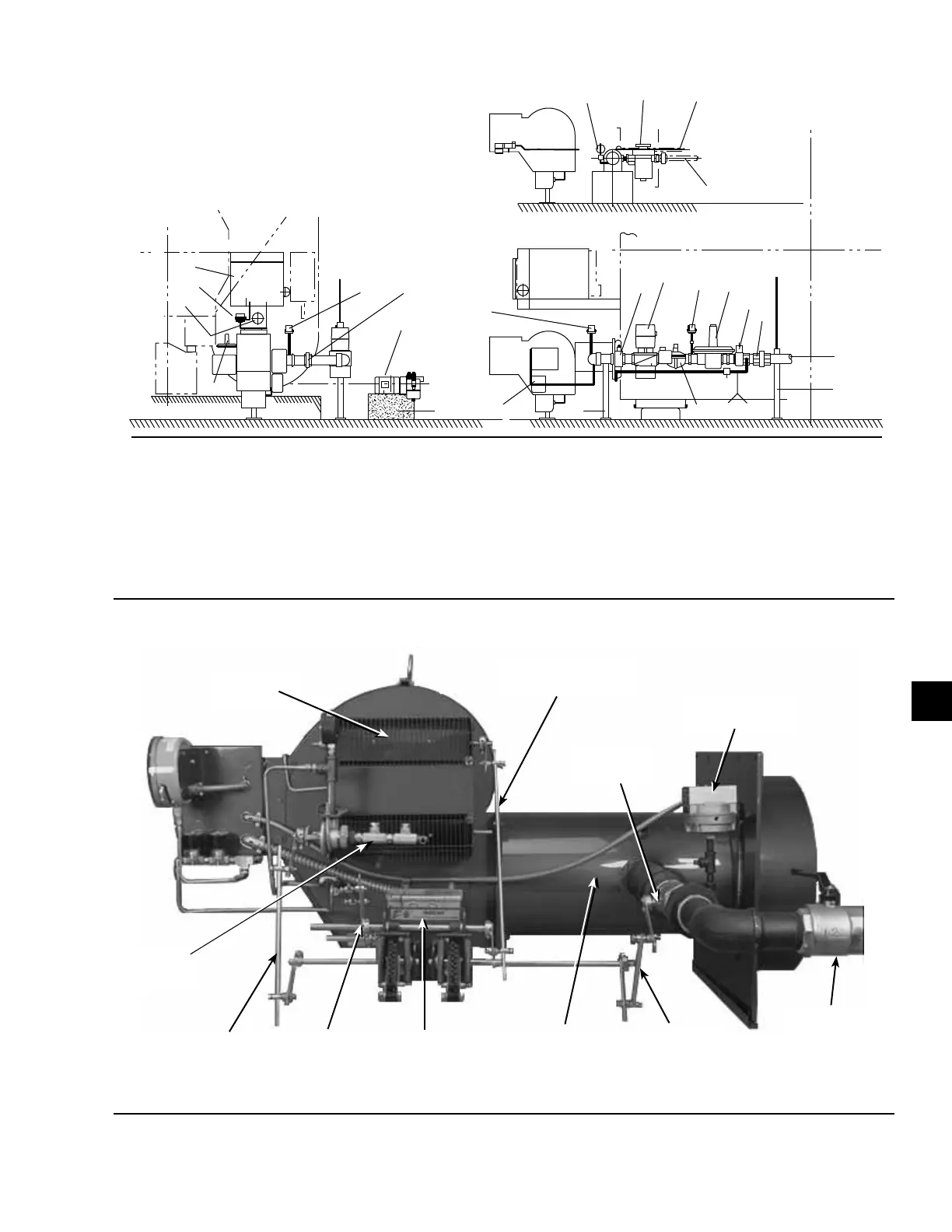
EasyManuals Logo

Johnson Controls YORK YPC Series User Manual

Johnson Controls YORK YPC Series
114 pages
To Next Page IconTo Next Page
To Previous Page IconTo Previous Page
Page #41 background imageLoading...
Page #41 background image
JOHNSON CONTROLS
41
SECTION 12 – BURNER INSTALLATION (POWER FLAME BURNERS)
FORM 155.17-N1
ISSUE DATE: 4/1/2013
12
ITEM NAME
01 Base (For Oil Pump Unit)
02 Support (For Oil Pump)
03 Gas Supply Piping
04 Oil Supply Piping
05 Oil Return Piping
06 Union
07 Main Gas Shut-O Cock
ITEM NAME
08 Main Gas Pressure Regulator
09 Low Gas Pressure Switch
10 Auxiliary Gas Valve
11 Pilot Regulator
12 Main Gas Shut-O Valve
13 Manual Leak Test Shut-O Valve
14 Gas Pressure Gauge
ITEM NAME
15 High Gas Pressure Switch
16 Manual Pilot Gas Shut-O Valve
17 Oil Pump Unit
18 Oil Filter
19 Oil Compound Gauge
20 Burner Unit
21 Burner Control Panel
NOTE: SOME OF THE EQUIPMENT LISTED
MAY NOT BE APPLICABLE TO ALL INSTALLATIONS
SHELL CENTER LINE
SHELL CENTER LINE
SHELL CENTER LINE
SHELL CENTER LINE
OIL RETURN
OIL SUPPLY
YORK
YORK
YORK
21
11
19
14
15
17
6
1
19
18
5
4
10
16 6
15
20
2
3
2
13
12
9
8
7
6
FIGURE 15 - TYPICAL BURNER ASSEMBLY FOR DIRECT-FIRED, G-MODEL UNITS
LD05308
00270VIP
Combustion Air
Damper Linkage Set
High Gas Pressure
Switch
Air Damper
Box
Modulating
Gas Valve
Blast Tube
Varicam Fuel Me-
tering System
Gas Valve
Linkage Set
Oil Valve
Linkage Set
Jack Shaft
Linkage Set
Oil Check
Valves
Manual
Gas Cock
FIGURE 16 - TYPICAL BURNER COMPONENTS (RIGHT-SIDE VIEW)

Table of Contents

Questions and Answers:

Question and Answer IconNeed help?

Do you have a question about the Johnson Controls YORK YPC Series and is the answer not in the manual?

Johnson Controls YORK YPC Series Specifications

General IconGeneral
BrandJohnson Controls
ModelYORK YPC Series
CategoryChiller
LanguageEnglish

Related product manuals