JOHNSON CONTROLS
82
SECTION 29 – ELECTRICAL CONNECTIONS
FORM 155.17-N1
ISSUE DATE: 4/1/2013
FLOW SWITCHES
The ParaFlow
TM
chiller/heater must mon i tor the flow
of water through the various heat ex chang er bundles in
order to operate correctly. There fore, flow switches or
differential pressure control switch es are re quired on
the chilled water, tower water and hot water (if ap pli-
ca ble) flow circuits to determine if flow is established.
The chilled water flow switch is a safety control. It
must be connected to prevent operation of the unit
whenever chilled water flow is stopped. One Chilled
Wa ter flow switch for each unit is al ways sup plied by
YORK and in clud ed with the unit’s ship loose parts. A
dif fer en tial pressure control switch, tower wa ter flow
switch, or a hot water flow switch (if ap pli ca ble) can
be pur chased through YORK as an extra or der op tion.
Oth er wise, the tower wa ter and hot water flow switch-
es must be sup plied by oth ers.
For in stal la tion of these switch es, re fer to the Unit Wa-
ter Pip ing and Hook-up section of this doc u ment. For
wir ing, con nect the chilled water flow switch to termi-
nals 1 and 12 on TB2 of the Digital Input Board. This
board is lo cat ed in side the unit mi cro panel.
For the tower water flow switch, connect the wires
to terminals 1 and 20 on TB2 of the Digital Input
Board. The hot water flow switch (if applicable) would
be con nect ed to terminals 1 and 82 on TB4 of the
Relay Board. See Figure 43 on page 83.
All Flow devices contact ratings are to be
5 milliamperes at 115 volts A.C.
CONTROL OF CUSTOMER SYSTEM PUMPS
Since ab sorp tion chillers require a dilution cycle of an
unpredictable length of time, it is mandatory that the
ParaFlow
TM
micro panel control the operation of
the following system pumps:
• Condenser Water (Tower water)
• Chilled Water
• Hot Water (when applicable)
YORK’s prescribed method to employ this pump con-
trol is to hard wire the pump starter control circuit
through the appropriate contacts on the relay board.
See Figure 41 on page 82.
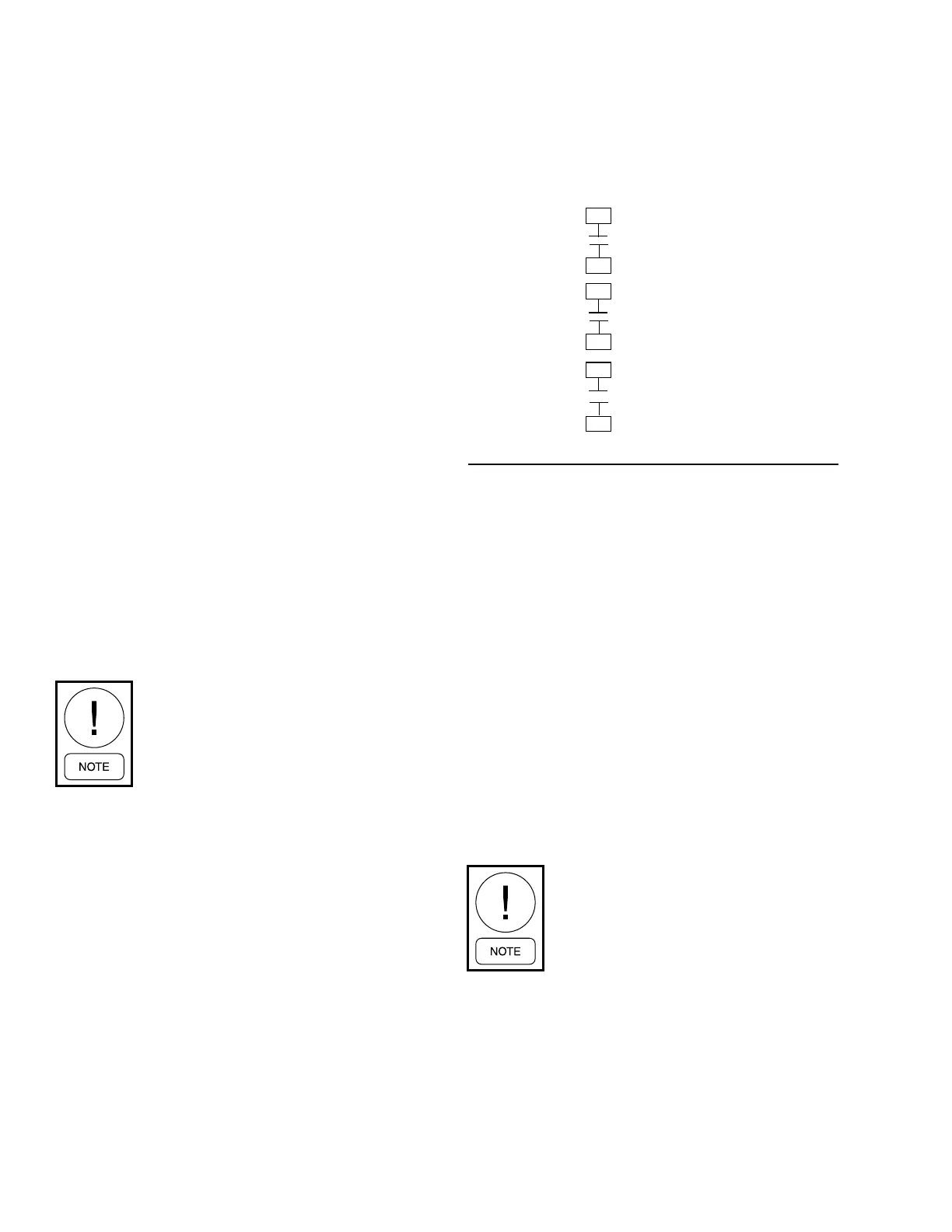
RELAY BOARD 031-01199-000
CONDENSER WATER
PUMP CONTACTS
HOT WATER
PUMP CONTACTS
CHILLED WATER
PUMP CONTACTS
55
56
87
88
44
45
FIGURE 41 - RELAY BOARD CONTACTS
LD05331
Should a customer insist on using another device,
such as an Energy Management System, to control the
pumps, that device must turn the pumps on and off as
a result of its direct interface with the contacts on the
relay board.
If there is a desire to interface the pumps with some de-
vice other than the ParaFlow
TM
micro panel, that device
must receive its instructions from the micro panel and
not from the Energy Management System.
Each con tact rat ing is 5 amps re sis tive at +/- 250 volts
A.C. and 30 volts D.C., 2 amp in duc tive (0.4 PF) +/-
250 volts A.C. and 30 volts D.C. Each 115 volt field-
con nect ed in duc tive load (i.e. relay coil, motor start er,
etc.) shall have a transient sup pres sor wired in parallel
with its coil, phys i cal ly lo cat ed at the coil. Spare tran-
sient sup pres sors and control cir cuit fuses are sup plied
in a bag in the control center.
Failure to adhere to the above
in struc tions could result in evaporator
tube freeze-up and unit crystalliza-
tion. Johnson Controls will not be re-
sponsible for damages to the unit, nor
cov er any charges under the unit war-
ran ty.
 Loading...


