JOHNSON CONTROLS
47
FORM 155.17-N1
ISSUE DATE: 4/1/2013
14
Prior to designing/installing oil pip ing
systems, all national, local and other
applicable codes, restrictions, and reg-
u la tions should re viewed to ensure to tal
compliance.
ParaFlow
TM
Units are designed for use with #2 fuel oil.
A two-pipe system (separate suction and return line)
must always be used. The oil pumps are preset at the
Power Flame factory with a two pipe system. The
pump war ran ty will be voided if a one pipe system
is installed.
Do not install manual valves in the return line between
the pump and the oil tank unless required by a specific
code. If a manual valve is required, an automatic relief
valve must be installed across the manual valve to en-
sure that oil will bypass directly back to the tank in
the event the manual valve is inadvertently left in the
closed position. It is always best to keep the oil return
SECTION 14 – OIL PIPING DESIGN
line at the same level or lower than the oil pump. Ex-
cess back pressure may damage the oil pump.
Do not use Teflon tape on any oil piping connec-
tions. Rigid pipe connected to the pump may cause ex-
cessive vibration. It is recommended that the connec-
tion to the pump be of copper tubing, complete with
a vibration damp en ing loop, on both the suction and
return lines. Copper tubing with flare fittings or iron
pipe is to be used on all installations. All units must
utilize the proper size and type of suction line oil fil-
ters. See Table 10 on page 90 in Appendix A at the
back of this document for prop er oil filter usage.
Some burners, even though they are strictly oil burn-
ers, re quire a gas flame ignitor pilot be used instead
of elec trode flame ignition. Usually any Power Flame
burner larger than a CR4-(G)O-25, or a burner that has
an oil us age ca pac i ty of greater than 60 gpm, requires
that a gas pilot be used.
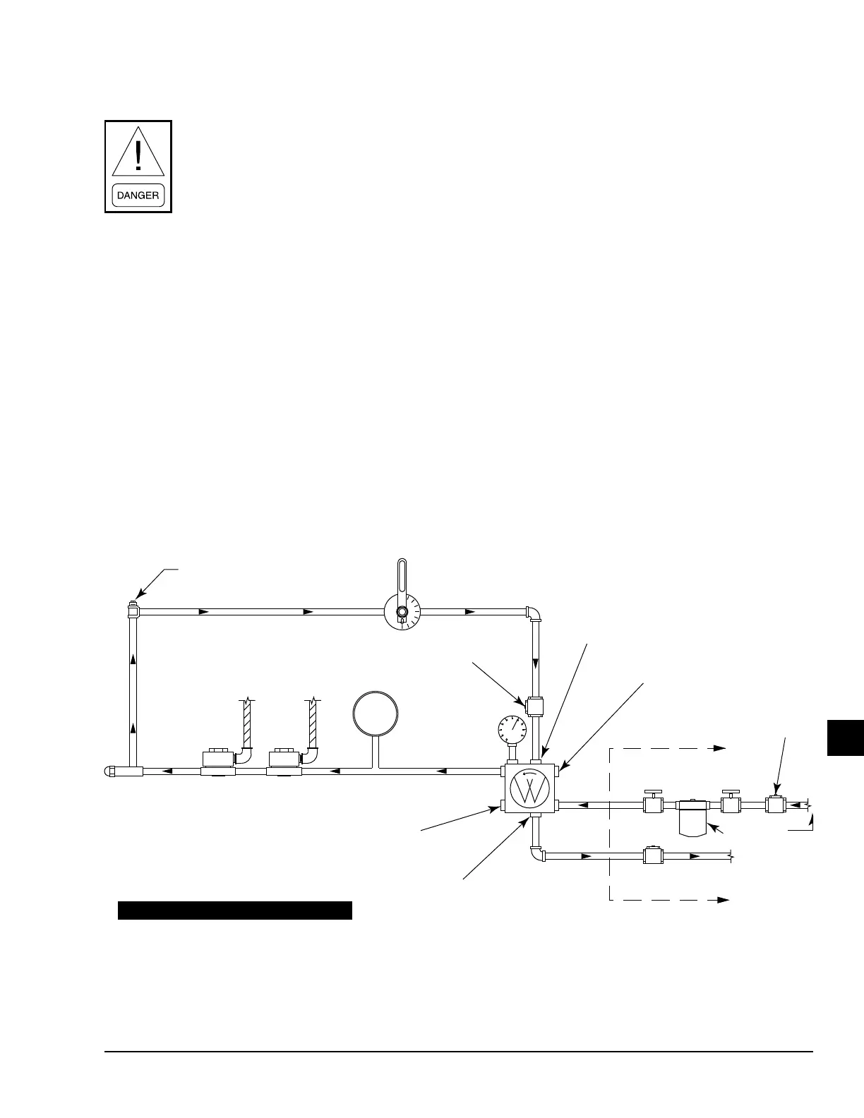
FIGURE 22 - TYPICAL SCHEMATIC OIL PIPING
LD05311
RETURN PRESSURE TRAP
NOZZLE
OIL SOLENOID VALVES
OIL PUMP
VACUUM GAUGE
INLET PORT
RETURN PORT
FIELD PIPED COMPONENTS
TO BE SUPPLIED BY CUSTOMER
CHECK VALVE
FILTER
CHECK VALVE
AT TANK
FUSIBLE LINK
VALVE
SHUTOFF
VALVE
INLET PORT
METERING VALVE
GAUGE
PRESSURE
TEST PORT
LOW OIL
PRESSURE SWITCH
CHECK VALVE
OPTIONAL RETURN PORT
1/8" ALLEN SCREW UNDER CAP
SCREW FOR NOZZLE OIL
PRESSURE ADJUSTMENT
DO NOT USE TEFLON TAPE ON OIL LINES
CAUTION: ALL FIELD COMPONENTS MUST BE MOUNTED IN
THE PROPER LOCATION AND DIRECTION OF OIL FLOW.
CAUTION: OIL SUPPLY MUST NOT EXCEED 3 PSI PER NFPA CODE
OIL
SUPPLY
OIL
RETURN LINE
 Loading...


