JOHNSON CONTROLS
25
SECTION 6 – UNIT WATER PIPING AND HOOK-UP
FORM 155.17-N1
ISSUE DATE: 4/1/2013
6
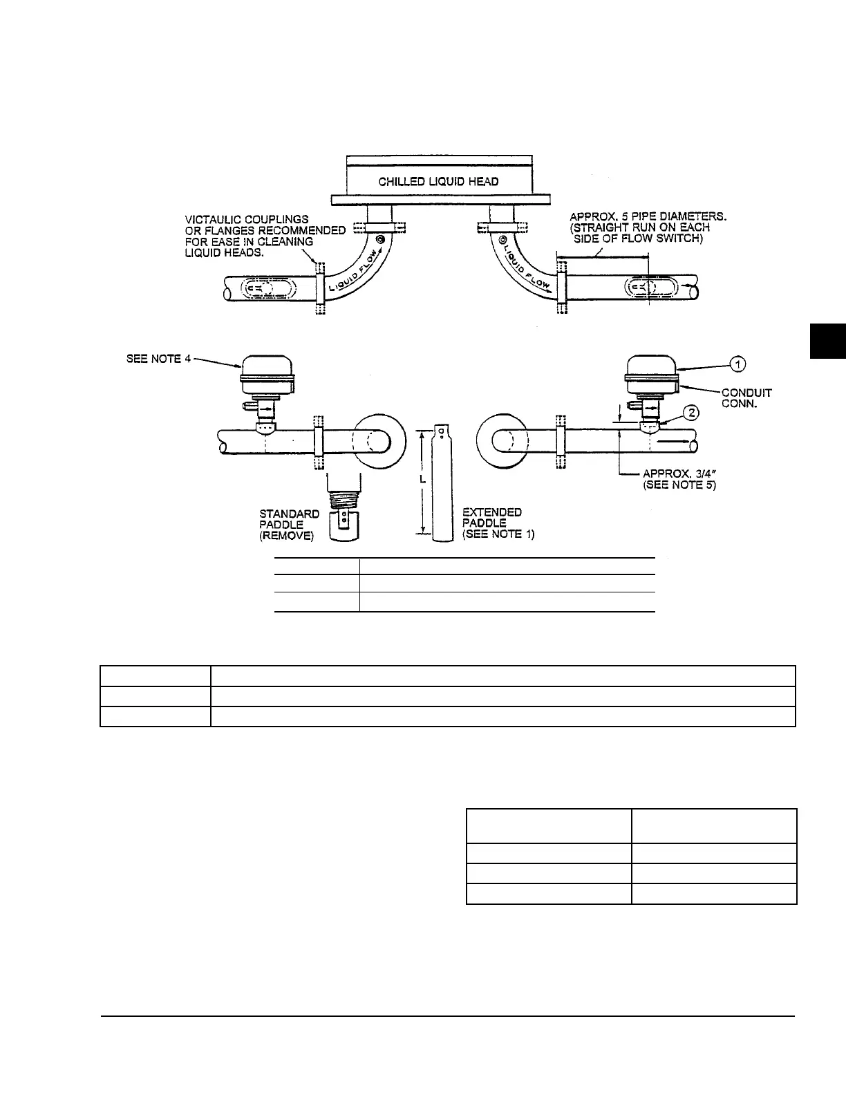
FIGURE 9 - INSTALLATION OF FLOW SWITCH
ld05303
ITEM DESCRIPTION
1 Switch, Flow Control (Supplied by YORK)
2 Coupling, Pipe, 1" x 1" Lg. (Not Supplied)
NOTES:
1. Adjust the Flow Switch Paddle to the size of the
pipe in which it is to be used. Trim extended pad
2. row mark on side of casting must point in same
direction as liquid ow.)
3. The Flow Switch can be installed in either the in-
let ow or outlet ow connections.
4. Before installing Item 2, make sure it is 1 inch
long, maximum.
DIAMETER OF PIPE
(INCHES)
"L" DIMENSION (INCHES)
5 4-5/8"
6 5-5/8"
8 and Larger Full Paddle
ITEM DESCRIPTION
1 Switch, Flow Control (Supplied by YORK)
2 Coupling, Pipe, 1" x 1" LG. (Not Supplied)
 Loading...


