JOHNSON CONTROLS
56
SECTION 17 – COMBUSTION AIR REQUIREMENTS
FORM 155.17-N1
ISSUE DATE: 4/1/2013
AIR PROVING SWITCH
(optional accessory supplied by others)
On some in stal la tions, an ad di tion al aux il ia ry safe ty in-
ter lock switch may be in stalled and wired into the Pow-
er Flame con trols cir cuit ry. This safe ty switch, along
with its sub or di nate controls (mo tor contactor, pres sure
reg u la tor, ven ti la tion unit and/or damp ers), can be used
to ensure am ple make-up fresh air is brought into the
equip ment room from the out doors at all times when
the burn er is run ning.
When the Start signal is sent from the YORK Mi cro
pan el to the burner control center, a 180-second timer
is start ed. All circuitry must complete its func tion with-
in this 180 second time frame so that the burner pan-
el’s “Main Flame On” con tacts can close. Oth er wise, a
“Warning – Burner Pan el Mal func tion” will ap pear on
the YORK pan el dis play and the burn er will need to be
manually restarted.
Consult the Power Flame “As Built” wiring schematic
for location of where the air proving connection ter mi-
nals are located.
It is preferred to interlock all automatic
opening louvers, grills, room dampers, or
ventilation fans so that they open during
unit operation. The temperature of the
mechanical room must not drop to a point
which may facilitate crystallization in the
event of a power failure. All mechanical
room openings should be allowed to close
during a power failure.
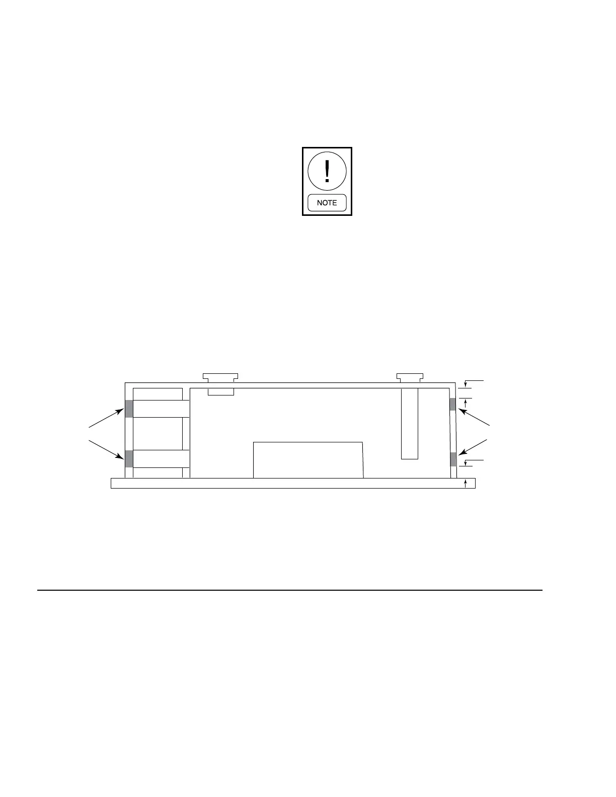
FIGURE 27 - COMBUSTION AND VENTILATION AIR IN MECHANICAL ROOMS
LD05316
LOUVERS/GRILLS
2
2
INTERSTITIAL
SPACE
MECHANICAL ROOM FLOOR
PARAFLOW
CHILLER/HEATER
MECHANICAL ROOM
OUTDOORS
12"
LOUVERS/GRILLS
12"
1
3
3
1
 Loading...


