JOHNSON CONTROLS
67
22
FORM 155.17-N1
ISSUE DATE: 4/1/2013
SECTION 22 – SEQUENTIAL DRAFT CONTROL (Motorized Draft Control)
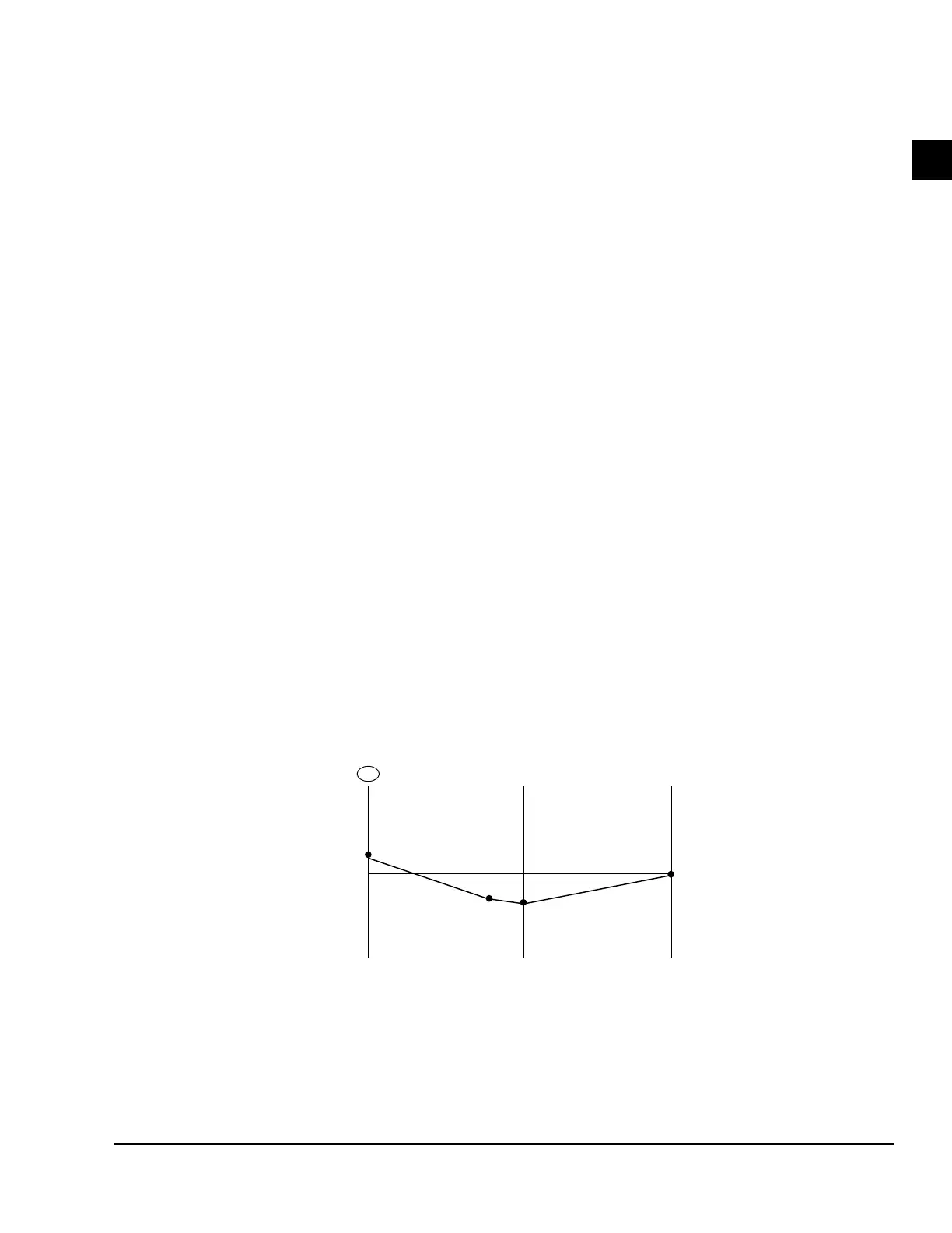
Figure 32 on page 67 and Figure 33 on page 68
depict a sequential draft control system. This type of
system incorporates an actuator motor mounted on top
of the damper assembly. The actuator arm is connected
to the damper blades through a linkage system to auto-
matically open or close the damper blades. The actua-
tor receives a signal from a separately mounted “Over-
fire Draft Control Panel” that constantly monitors the
present draft at the outlet of the first stage generator.
The signal to the actuator motor constantly adjusts the
damper blades to provide the available draft required
per burner loading.
Motorized draft control is suitable for ap pli ca tions
where multiple gas-fired appliances will be ducted into
one com mon chimney system. In this case, each unit
will require its own draft control system. (Motorized
draft control may be used for one unit/one chimney
ap pli ca tions, if desired, over the standard barometric
damper control).
When multiple ParaFlowTM Chiller-Heaters are to be
duct ed into a common breeching or chimney system, it
is recommended that separate draft control system be
pro vid ed for each unit.
BACKDRAFT DAMPER
The Johnson Controls supplied manual backdraft
damper can be modified (in the factory if ordered, or
in the field) to mount the motor driver. The motor is
controlled from a draft control panel which senses the
pressure at the out let of the high-temperature genera-
tor. The draft control panel is available from Johnson
Controls to ship with the chiller (see Figure 29 on
page 63 for drawing of the motorized damper). The
pan el is wired to the burn er panel and damp er motor
in the field, and the pres sure is sensed through a small
line field-con nect ed to the outlet of the chiller-heat er.
Not recommended to mount vertically
reasons:
1. Not best position for optium draft (See Figure 32
on page 67)
2. Creates more area for positive pressure. could
leak combustables into equipment room.
3. More difcult to control combution chamber
pressure.
A
B
C
D
TOP OF
CHIMNEY
SYSTEM
BASE OF
VERTICAL
CHILLER-HEATER
OUTLET
1
GAUGE
PRESSURE
(IN. WATER)
0
+
–
Point B is downstream
of motorized damper
FIGURE 32 - GAUGE PRESSURE PROFILE / CHIMNEY SYSTEM WITH SEQUENTIAL DRAFT CONTROL
LD05357
NOTES:
1. dP between A and B due to transition piece and motorized damper. Damper automatically controls to maintain of water at A. The actual
dP is variable and depends on the momentary gauge pressure C.
2. Maximum draft (minimum gauge pressure) occurs at base of vertical section of chimney (C). With sequential draft control, this valve is
allowed to drift with prevailing ambient conditions. Motorized damper controls to maintain steady gauge pressure at A.
 Loading...


