JOHNSON CONTROLS
51
15
FORM 155.17-N1
ISSUE DATE: 4/1/2013
SECTION 15 – OIL LINE SIZING
It is very important to properly size the oil suction line
and oil filter, to provide fuel flow to the burner with-
out exceeding 10" suction pressure (vacuum) at the oil
pump suction port.
The method to properly size copper tubing is outlined
below. Consult the burn er man u fac tur ers ser vice de-
part ment for sizing as sis tance re gard ing iron pipe.
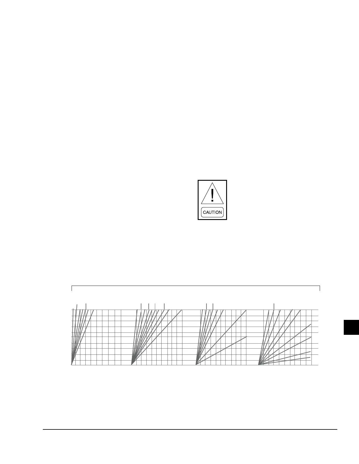
INSTRUCTIONS FOR USING OIL LINE SIZING
GRAPHS:
1. Check oil pump “GPH Suction Capacity” from
“Absorption Burner Sizes” table or the “Oil Pump
Suc tion Capacity and Filter Selection Chart” in
Appendix A at back of this doc u ment.
2. Measure total tube length (horizontal and verti-
cal) from the end of the line in the tank to the
connection at the oil pump.
3. Choose the appropriate graph based on the tubing
size. Read up from the horizontal axis “Total Feet
of Copper tubing” to “Suction Capacity in G.P.H.
4. Read to the left until the vertical axis is reached.
This is the vacuum required to draw oil through
the length of tube selected.
5. If the installation has lift (vertical distance the
fuel unit is above the top of the tank), add 1" of
vacuum for every 1 foot of lift.
6. Add the two values obtained in steps 4 and 5.
7. If the total obtained in step 6 is over 10" vacu-
um, move to the next graph to the right (increase
tubing size) and re-calculate the total inches of
vacuum.
8. These instructions do not allow for any added
restrictions, such as the line lter, elbows, sharp
corners, check valves, etc. Suction line vacuum
values will vary from one manufacturer to an-
other. A good rule of thumb to determine total
vacuum for suction line siz ing is to add 10% to
the vacuum obtained in step 6.
It is always safe to size the re turn line from
the pump to the tank at the same size as
the selected suc tion line.
55
50
35
30
30
75
50
40
25
20
60
45
35
25
20
200
75
150
125
100
175
50
25
300
250
200
150
125
100
75
50
25
50
100
150
200
250
300
350
400
450
500
50
100
150
200
250
300
350
400
450
500
50
100
150
200
250
300
350
400
450
500
50
100
150
200
250
300
350
400
450
500
OIL LINE SIZING (COPPER TUBING – #2 FUEL OIL ONLY)
SUCTION CAPACITY IN G.P.H
TOTAL FEET OF 3/8" O.D.
COPPPER TUBING
TOTAL FEET OF 1/2" O.D.
COPPPER TUBING
TOTAL FEET OF 5/8" O.D.
COPPPER TUBING
TOTAL FEET OF 3/4" O.D.
COPPPER TUBING
INCHES OF VACUUM AT FUEL UNIT
20
18
16
14
12
10
8
6
4
2
FIGURE 26 - OIL LINE SIZING GRAPHS
LD05315
 Loading...


